System Overview 2-9
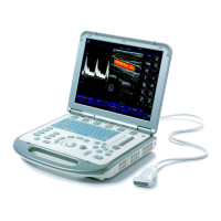
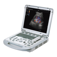
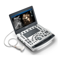
2.6 Introduction of Each Unit
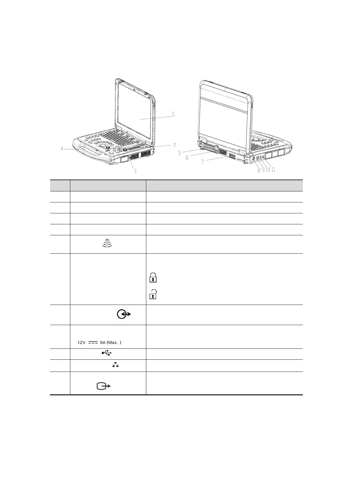
No.
Name Function
1 Monitor Displays the images and parameters during scanning.
2 Control Panel Operator-system interface or control.
3 CW pencil probe port Connects the pencil probe to the main unit
4 Handle Used for carrying the system.
5
Probe port
Connects a probe to the main unit; or connects a probe
extend module.
6 Transducer locking lever
Locks or unlocks the probe connected with the main
unit.
: locked symbol
: unlocked symbol
7
I/O extend port
Connects the I/O extend module.
8
Power input port
Connects the power adapter.
9 USB port Connects USB devices.
10
Network port
Connects the network.
11
S-Video separate video
output
Connects DVR recorder or video printer.

 Loading...