5-106
Resetting the origin
5 Maintenance and Inspection
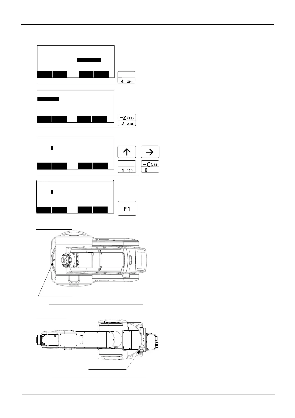
(1) J1 axis origin setting
1) Press the [4] key on the menu screen, and dis
-
play the Origin/Brake selection screen.
2) Press the [2] key, and display the Brake release
selection screen.
3) Release the brake of the J1 axis.
Input "1" into the J1 axis. Set "0" to other
axes.
4) Confirm the axis for which the brakes are to be
released.
5) Pressing the [F1] key is kept with the enabling
switch of T/B pressed down. The brake is
released while pressing the key.
6) Move the J1 axis slowly toward the front using
both hands. Align the pinhole of the lower part of
the shoulder and the pinhole at the base
section, feed through the origin jig (φ6) into the
pinholes and fasten.
<MENU>
1.FILE/EDIT 2.RUN
3.PARAM.
4.ORIGIN/BRK
5.SET/INIT. 6.ENHANCED
CLOSE
123
<ORIGIN/BRAKE>
1.ORIGIN 2.BRAKE
CLOSE
123
<BRAKE>
J1:(
0 )J2:( 0 )J3:( 0 )
J4:( 0 )J5:( 0 )J6:( 0 )
J7:( 0 )J8:( 0 )
CLOSE
123
REL.
<BRAKE>
J1:(
0 )J2:( 0 )J3:( 0 )
J4:( 0 )J5:( 0 )J6:( 0 )
J7:( 0 )J8:( 0 )
CLOSE
123
REL.
<BRAKE>
J1:(
0 )J2:( 0 )J3:( 0 )
J4:( 0 )J5:( 0 )J6:( 0 )
J7:( 0 )J8:( 0 )
CLOSE
123
REL.
<BRAKE>
J1:(
1 )J2:( 0 )J3:( 0 )
J4:( 0 )J5:( 0 )J6:( 0 )
J7:( 0 )J8:( 0 )
CLOSE
123
REL.
Pinhole (J1 axis)
Diagram of the robot viewed from the top
Diagram of the robot viewed from the top
Pinhole (J1 axis)
RV-13F
series
RV-4F/7F series
 Loading...
