2Unpacking to Installation
Setting the origin
2-19
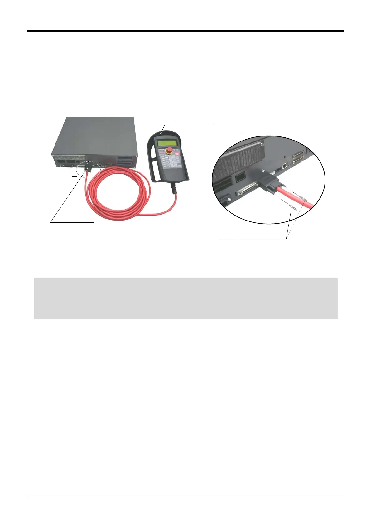
(2) CR751 controller
Explain the installation method of T/B below.
1) Check that the POWER (power supply) switch of the robot controller is OFF.
2) Connect the T/B connector to the controller’s T/B connector. Make sure to fix it securely by fastening the
hand locks (in 2 places), as shown in Fig. 2-10.
Fig. 2-10 : Installing and removing the T/B (CR751controller)
The installation of T/B is finished.
A部
ティーチングボックス
(T/B)
T/B接続用コネクタ
A部詳細
手回しロック(2箇所)
Controller
T/B connector
Teaching pendant
Details of the A section
A
Hand lock (Two places)
T/B connector
Note) Although the figure is RV-4F/7F series controller,
and RV-13F series is also the same.
◇◆◇ If error C0150 occurs ◇◆◇
At the time of the first power supply injection, error:C0150 (the serial number of the robot arm has not been
set up) occur the robot after purchase.
Parameter: Please input the serial number of the robot body into RBSERIAL. Refer to "instructions manual /
controller setup, and basic operation & maintenance" for the operation method.
 Loading...
