3Installing the option devices
Installing the Forearm external wiring set/ Base external wiring set
3-73
3) Install Forearm external wiring set on the position where cable clamp box was being installed, by using original
three fixing screws. Installs carefully so that the cable etc may not be inserted.
4) Connects the cable pulled out to the tool or sensor etc which customer will use. The Outlet and cable names
of each cables are shown in Table 3-10. You can fix the cable by using the screw holes on the robot arm.
(refer to separate "Standard Specifications Manual")
Note) Although the connector is attached to the customer wiring side of the hand input cable, it can use by
cutting. Pin assign of the hand input cable is shown in Table 3-11.
Table 3-11 : Pin assign of hand input cable
5) Confirms after the connection that the cable interferes with neither the robot arm nor the peripheral device
and the not having receive stress. And, confirms that the tool, the sensor, etc. operate correctly.
This completes installing the Forearm external wiring set.
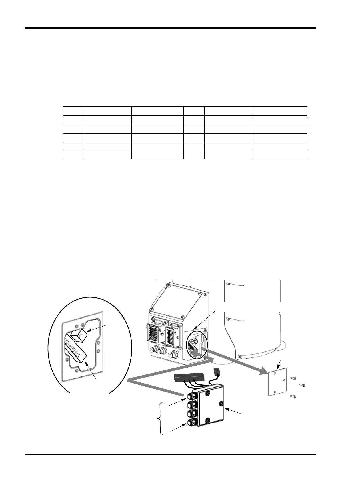
(2) Installing the Base external wiring set
The installation summary of the Base external wiring set is shown in Fig. 3-6. Mounts this option instead of the
CONBOX cover R.
1) Loosen the fixing screws (three M4x16 screws) of CONBOX cover R and remove the box.
2) The connector: LAN, CNOP1 is in CONBOX cover R. The connector is previously attached to the connector
LAN. Removes this connector.
3) Connects the connector of Base external wiring set to the connector of robot arm side. Connect with the
same name.
Fig.3-6 : Installing the Base external wiring set
Color Signal name
Connector (HC)
Note1)
Note1) Shows the pin number of the connector previously attached to the customer wiring side.
Connector type: 1-1827864-6, Pin type: 1827570-2, Maker: Tyco Electronics Japan G.K.
Color Signal name
Connector (HC)
Note1)
Purple HC1 A1 Red HC5 B1
Brown HC2 A2 White HC6 B2
Blue HC3 A3 Gray HC7 B3
Black HC4 A4 Pink HC8 B4
Yellow +24V A6 Green +24G(RG) B6
CONBOX cover R
Connecting connector (two connectors)
(Inside the CONBOX cover R)
<1>
<2>
<3>
<4>
~
Customer wiring side
Cable outlet
(Refer to Table 3-12.)
Base external wiring set
LAN
CNOP1
Connectors details
CNOP1
LAN
 Loading...
