ELECTRICAL SYSTEM
12-4
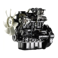
1.2.3 Inspecting regulated voltage
(IC regulator integral type)
(1) Disconnect (+) battery terminal and connect an
ammeter across the line.
(2) Connect a voltmeter between terminal L and ground.
(3) The indication of the voltmeter must be 0 when the
starter switch is OFF.
The indication of the voltmeter must be considerably
lower than the battery voltage when the starter switch is
ON (engine OFF).
(4) Start the engine with the ammeter terminals
disconnected.
(5) Read the voltmeter (regulated voltage) while the
ammeter reading is 5 A or lower, 2500 min
-1
, and lamp
switches OFF.
Checking regulated voltage
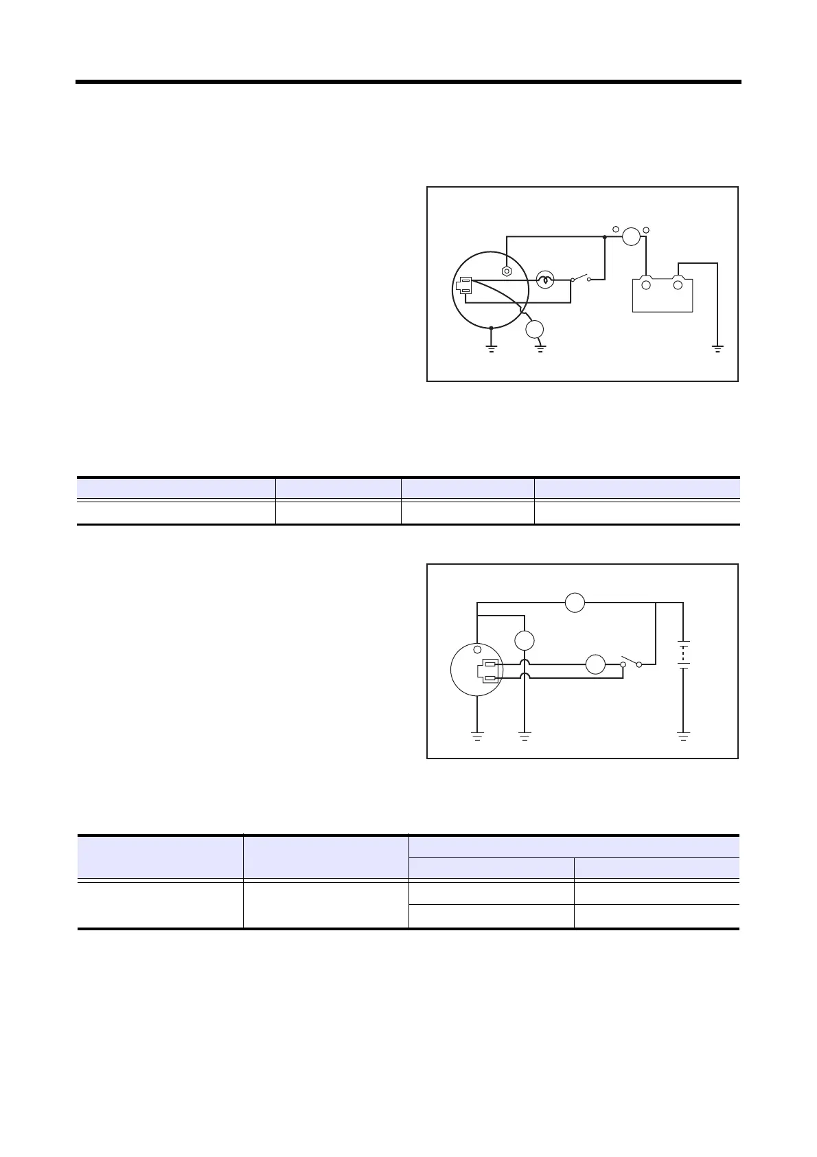
1.2.4 Inspecting output
(a built-in IC regulator type)
(1) Disconnect the battery ground cable.
(2) Connect B terminal of the alternator to the ammeter,
then connect the voltmeter between B terminal and
ground.
(3) Connect the battery ground cable.
(4) Start the engine.
(5) Immediately apply all loads such as lamps.
(6) Increase the engine speed and measure the maximum
output current at the specified alternator rotation speed
with the voltmeter indicated the specified value.
(7) If the measured value meets the standard, the output is
normal.
Inspecting regulated voltage
12V
L
R
A
V
Switch
Ammeter
Voltmeter
Battery
Item Spec Standard Condition
Regulated voltage (at 20°C [68°F]) 12 V - 50 A 14.4 to 15.0 V
5000 min
-1
, 5A or lower, 20°C [68°F]
L
R
B
A
V
Charge
lamp
Switch
Ammeter
Battery
Voltmeter
Item Spec
Standard
Terminal voltage/current Alternator rotation speed
Output characteristics
(when hot)
12V - 50A
13.5V / 33A or higher
2500 min
-1
13.5V / 47A or higher
5000 min
-1
 Loading...