SPECIFICA TIONS
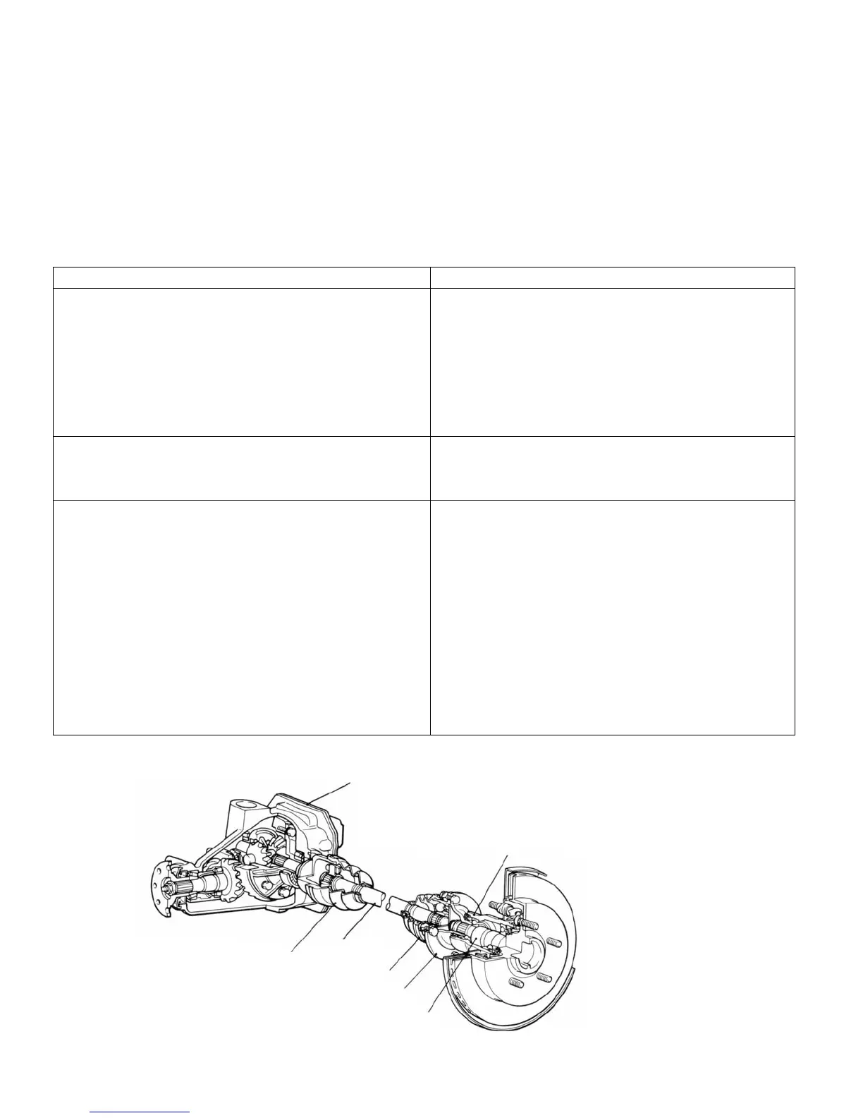
The differential carrier and axle housing have been
separated from each other, and T.J. and B.J. drive
shafts arranged in between. They drive the axle shafts.
The axle shaft is supported by ball bearings (inner and
outer) in the axle housing and are coupled with the drive
shaft with the companion flange in between.
The front of the differential carrier is supported elastically
on the rear suspension crossmember via the differential
support and the rear side via the differential support
member.
Items Specifications
Axle shaft
Type Semi-floating type
Shaft dimensions
Outer bearing portion dia. mm (in.) 35 (1.38)
Inner bearin
ortion dia. mm
in.
28
1.1 0
Center
ortion dia. mm
in.
34.5
1.36
Overall len
th mm
in.
245.4
9.7
Bearin
0.D. x I.D. Outer mm
in.
72 x 35
2.83 x 1.38
Inner mm (in.) 58 x 28 (2.28 x 1.10)
Drive shaft
Joint t
pe Outer B.J.
Inner T.J.
Length (joint to joint) x diameter mm (in.) 395 x 28 (15.6 x 1.10)
Differential
Reduction gear type Hypoid gear
Reduction ratio 3.545
Differential
ear t
pe and confi
uration
Side
ear Strai
ht bevel
ear x 2*
Pinion
ear Strai
ht bevel
ear x 4
Number of teeth
Drive gear 39
Drive
inion 11
Side
ear 16
Pinion Gear 10
Bearin
0.D. x I.D. Side mm
in.
82.500 x 45.242
3.25 x 1.78
Front mm
in.
68.263 x 30.163
2.69 x 1.19
Rear mm
in.
76.200 x 36.513
3.00 x 1.44
Final drive gear backlash adjustment method Screw type
*.
Denotes the gear (L.H.) which is in a single body with the viscous coupling.
Differential carrier
11 N0002
POWER-TRANSMISSION COMPONENTS - Rear Axle 2-13
REAR AXLE
Trailing arm
(Axle housing)
T.J.
Drive shaft
B.J
.
Companion flange
Axle shaft
 Loading...