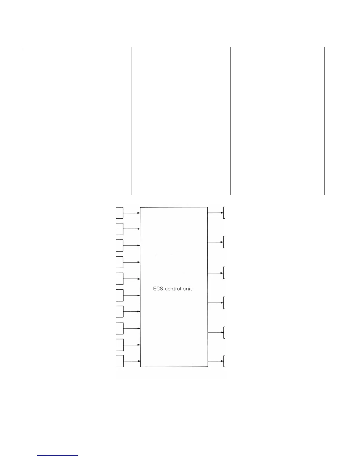
SYSTEM BLOCK DIAGRAM
Parts Function Mounting position
Sensor
ECS switch Control mode selection switch Meter bezel
Steering wheel angular velocity sensor Detects turning direction and Column switch
an
ular velocit
of steerin
wheel Under front seat
LH
G-sensor Detects u
/down vibration of vehicle
Vehicle speed sensor Detects speed of vehicle Transmission case
Throttle bod
Throttle position sensor Detects throttle opening Brake pedal bracket
Sto
lam
switch Detects condition of brake
edal Built in shock absorber
x 4
Position detection switch Detects dam
in
conditions of
shock absorbers
Actuator
ECS indicator lam
Indicates control mode Inside combination meter
Damping force changeover actuator Orifice changeover of inside of Built in shock absorber (x 4)
shock absorber
ECS control unit System control Right side of luggage compartment
Diagnosis connector Output of safe diagnosis code Side of junction block
ECS switch
ECS indicator lamp
Steering wheel angular velocity sensor
G-sensor
F.R. damping force changeover actuator
Vehicle speed sensor
F.L. damping force changeover actuator
Throttle position sensor
Stop lamp switch
R.R. damping force changeover actuator
F.R. position detection switch
F.L. position detection switch
R.L. damping force changeover actuator
R.R. position detection switch
R.L. position detection switch
Diagnosis connector
DRIVE-CONTROL COMPONENTS - Electronic Control Suspension (ECS) 3-9
MAIN PARTS AND THEIR FUNCTIONS

 Loading...