h
n
y
.y
'0
is
lS
~r
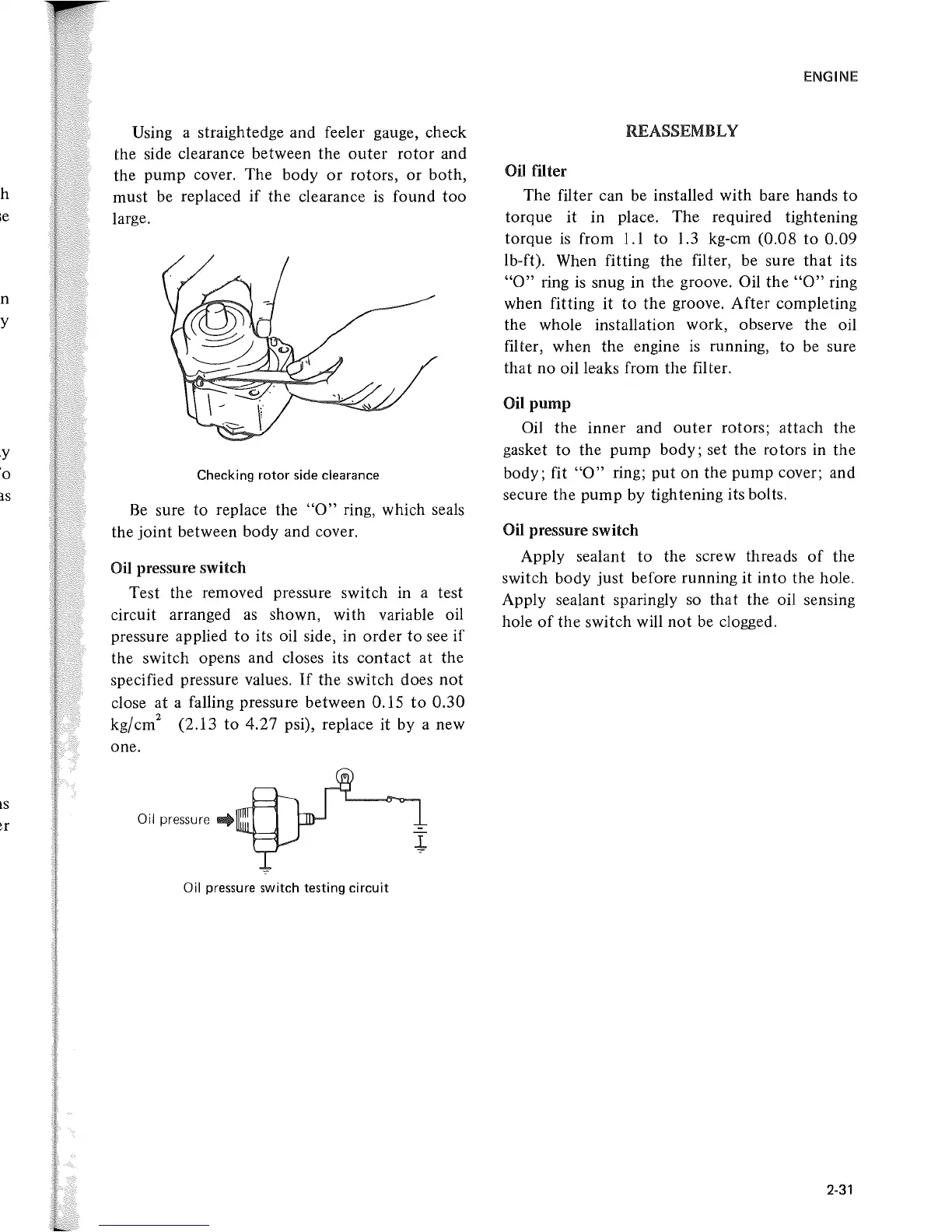
Using a straightedge and feeler gauge, check
the
side clearance between the
outer
rotor
and
the
pump
cover. The body
or
rotors, 01'
both,
must be replaced
if
the
clearance
is
found
too
large.
Checking rotor side clearance
Be
sure
to
replace the
"0"
ring, which seals
the
joint
between body and cover.
Oil pressure switch
Test
the
removed pressure switch in a test
circuit arranged
as
shown, with variable oil
pressure applied
to
its oil side, in
order
to
see
if
the switch opens and closes its
contact
at the
specified pressure values.
If
the switch does
not
close
at
a falling pressure between 0.15
to
0.30
kg/cm
2
(2.13
to
4.27 psi), replace it
by
a new
one.
Oil
pressure
..
Oil
pressure switch testing circuit
ENGINE
REASSEMBLY
Oil filter
The filter can be installed with bare hands
to
torque
it
in place. The required tightening
torque
is
from
1.1
to
1.3 kg-cm (0.08
to
0.09
Ib-ft). When fitting the filter, be sure
that
its
"0"
ring
is
snug in the groove. Oil
the
"0"
ring
when fitting
it
to
the
groove. After completing
the whole installation work, observe the oil
filter, when the engine
is
running, to be sure
that
no oil leaks from the filter.
Oil
pump
Oil the inner and
outer
rotors; attach the
gasket
to
the pump body; set the rotors in the
body; fit
"0"
ring;
put
on
the
pump
cover; and
secure the
pump
by tightening its bolts.
Oil pressure switch
Apply sealant
to
the screw threads
of
the
switch body just before running it
into
the hole.
Apply sealant sparingly so
that
the oil sensing
hole
of
the
switch will
not
be clogged.
2-31
 Loading...