1
• Control rack and pinions
Inspect the rack and pinions for
tooth
wear
and damage. Badly worn
or
damaged rack and
pinions must be replaced.
•
Tappet
Inspect each
tappet
for wear at
its.
sliding
surface, roller and shaft.
A damaged
or
exces-
sively worn
tappet
must be replaced.
Injection nozzles
(I)
Inspect each nozzle for damage, paying
particular attention to its needle valve.
If
the needle valve
is
not
seating tight,
as
evidenced by its contact pattern,
or
if
any
part
of
the nozzle
is
damaged, replace the
whole nozzle assembly.
(2)
Check to be sure
that
pressure springs are
in good condition, free from any signs
of
weakening.
(3)
Each nozzle assembly
must
be tested for
spray pattern after its reassembly. The
testing
method
will be explained in "Re-
assembly," below.
REASSEMBLY
Fuel fIlter
(1)
When setting the element, be sure
that
the
"0"
ring fits snugly. With the element set
properly and
"0"
ring in place, tighten the
retaining
nut
fully.
(2) Secure the filter assembly
to
the support.
Fuel
injection pump
(1)
Insert the barrel
into
the
pump
housing by
aligning its
notch
with
the
dowel
of
adjust-
ing plate.
(2)
Fit
"0"
ring to valve holder.
(3) Insert spring seat, gasket and valve assembly
into
the valve holder, and run the holder
into the
pump
housing. With
the
wrench,
tighten the holder in place to compress the
"0"
ring fully.
ENGINE
(4) Feed the control rack
into
the
pump
housing.
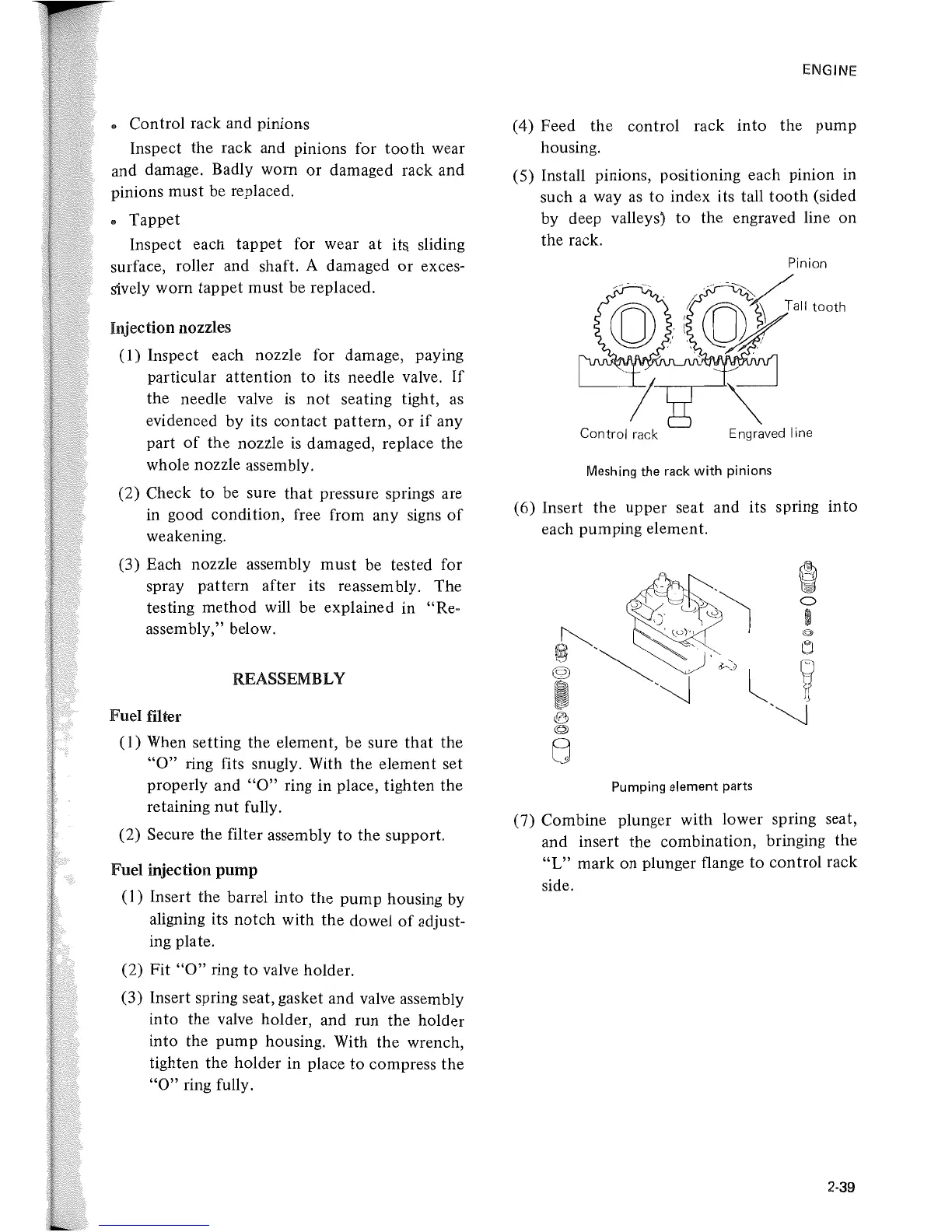
(5)
Install pinions, positioning each pinion in
such a way
as
to index its tall
tooth
(sided
by deep valleys) to the engraved line on
the rack.
Control
rack
Engraved line
Meshing the rack with pinions
(6)
Insert the upper seat and its spring into
each pumping element.
Pumping element parts
(7) Combine plunger with lower spring seat,
and insert the combination, bringing the
"L"
mark on plunger flange to control rack
side.
2-39
 Loading...