the delivery valve and spring in place
and with the injection pipes properly
installed: this
is
an alternate checking
method.
In
this case, disconnect No. I
pipe from its nozzle holder. Using a
socket wrench at the crank pulley nut,
gradually
turn
over engine crankshaft to
let No. I pumping element force fuel
out
of
the pipe. The
moment
the
fuel starts
swelling
out
of
the pipe
is
the
start
of
injection. This will occur approx. I deg.
behind the standard injection timing.
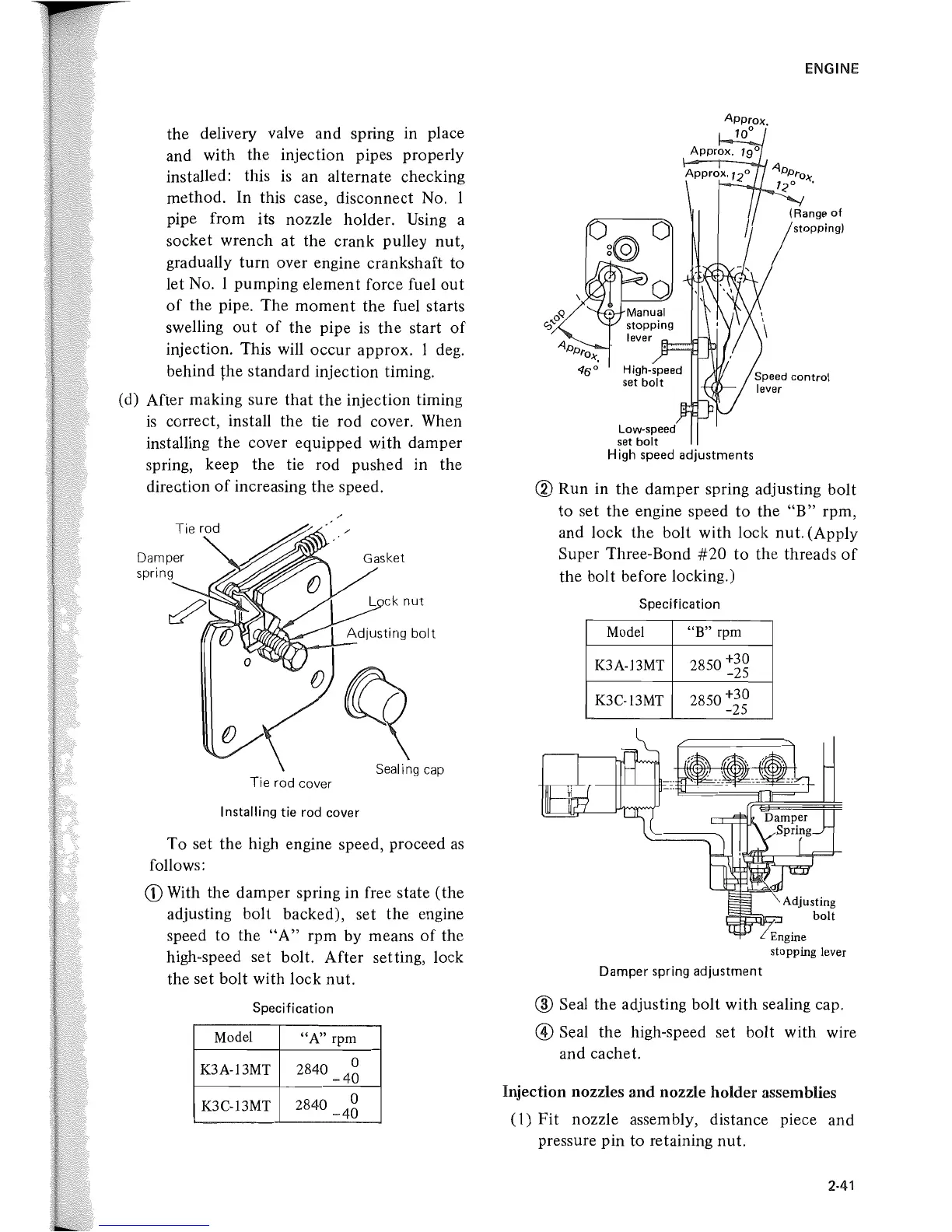
(d) After making sure
that
the injection timing
is
correct, install the tie rod cover. When
installing the cover equipped with damper
spring, keep the tie rod pushed in the
direction
of
increasing the speed.
Damper
Sealing cap
Tie rod cover
Installing tie rod cover
To set the high engine speed, proceed
as
follows:
CD
With the damper spring in free state (the
adjusting bolt backed), set the engine
speed
to
the
"A"
rpm by means
of
the
high-speed set bolt. After setting, lock
the set bolt with lock nut.
Specification
Model
"A"
rpm
K3A-13MT 2840
0
-40
K3C-13MT
2840
0
-40
Low-speed
set
bolt
High
speed adjustments
ENGINE
® Run in the damper spring adjusting bolt
to set the engine speed to the
"B"
rpm,
and lock the bolt with lock nut. (Apply
Super Three-Bond
#20
to the threads
of
the bolt before locking.)
Specification
Model
"B" rpm
K3A-13MT
2850 +30
-25
K3C-13MT
2850 +30
-25
Damper spring adjustment
® Seal the adjusting bolt with sealing cap.
@ Seal the high-speed set bolt with wire
and cachet.
Injection nozzles and nozzle holder assemblies
(1)
Fit nozzle assembly, distance piece and
pressure pin to retaining nut.
2-41
 Loading...