5 - 4 5 - 4
MELSEC-Q
5 SETTINGS AND PROCEDURES UP UNTIL OPERATION
5.4 Connection with a Console, Debugger
This section explains the connection methods of a personal computer with a console.
(1) Connection method
(a) Connection with a PC/AT personal computer
Cables need to be produced by the users to make a connection.
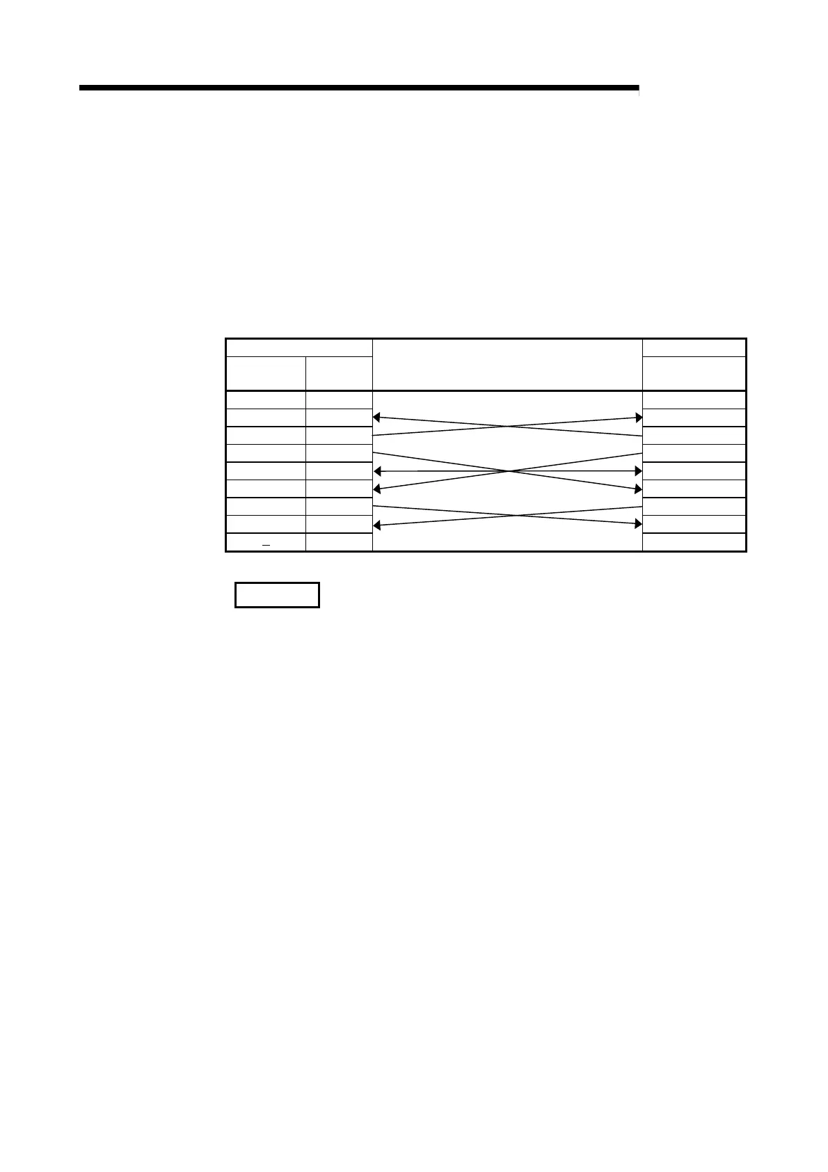
(2) Cable wiring
The wiring of the user-created cable is show below.
QD51 (-R24) side Console side
Signal name Pin number
Cable connection and signal direction
(Connection example of full or half duplex
communication)
Signal name
CD 1 CD
RD(RXD) 2 RD(RXD)
SD(TXD) 3 SD(TXD)
DTR(ER) 4 DTR(ER)
SG 5 SG
DSR(DR) 6 DSR(DR)
RS(RTS) 7 RS(RTS)
CS(CTS) 8 CS(CTS)
9
CAUTION
The pin arrangement on the console side differs depending on the personal
computer.
If the cable is made by the user, be sure to make the cables only after confirming the
interface specifications for the personal computer you are using.
 Loading...

