3 - 43 3 - 43
MELSEC-Q
3 SPECIFICATIONS
3.8 List of Input/Output Signals From/To the Programmable controller CPU
The QD51 (-R24)'s input/output signals are explained.
The following I/O signal assignment is based on the case where the start I/O No. of the
QD51 (-R24) is "0000" (installed to slot 0 of the main base unit).
Device X is an input signal from the QD51 (-R24) to a programmable controller CPU.
Device Y is an output signal from the programmable controller CPU to the QD51
(-R24).
The input/output signal list for the programmable controller CPU is shown in the
following table.
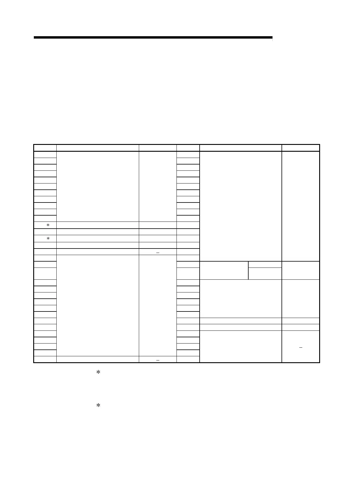
Device No. Signal Content Reference Section Device No. Signal Content Reference Section
X00 Y00
X01 Y01
X02 Y02
X03 Y03
X04 Y04
X05 Y05
X06 Y06
X07 Y07
X08 Y08
X09 Y09
X0A
General input Section 3.8.1 (1)
Y0A
X0B
1
Multitask execution start signal Section 3.8.1 (2) Y0B
X0C Multitask execution interrupt signal Section 3.8.1 (3) Y0C
X0D
2
QD51 (-R24) system down signal Section 3.8.1 (4) Y0D
X0E QD51 (-R24) operating status signal Section 3.8.1 (5) Y0E
X0F Use prohibited
Y0F
X10 Y10
General Output Section 3.8.2 (1)
X11 Y11 BASIC Task 1
X12 Y12
General output/
Start Task No. Designation
signal
BASIC Task 2
Section 3.8.2 (2)
X13 Y13
X14 Y14
X15 Y15
X16 Y16
X17 Y17
X18 Y18
General Output Section 3.8.2 (1)
X19 Y19 Task Start Signal Section 3.8.2 (3)
X1A Y1A Reset Request Signal Section 3.8.2 (4)
X1B Y1B
X1C Y1C
X1D Y1D
X1E
General input Section 3.8.1 (1)
Y1E
X1F Use prohibited
Y1F
Use Prohibited
1 The multitask execution start signal (X0B) is a signal that announces whether
access to the QD51 (-R24) by the programmable controller CPU is possible or
not. Use it as the system program interlock signal. (It goes ON when a BASIC
program is run.)
2 If the QD51 (-R24) system down signal (X0D) goes ON, start up the
programmable controller CPU again. (Power supply reset, CPU module, QD51
reset)
 Loading...

