Motorola Confidential Proprietary
V975/V980/C975/C980Manual Test Procdures
2-8
Draft 1.0
Non-Signaling Test Procedures
(GSM/DCS/PCS)
To perform non-signaling test procedures, the user is
required to be familiarized with sending test commands
to the phone under test. The test commands are sent
using a computer.
In order to successfully send test commands to the phone
under test, the phone needs to be in suspend mode.
Follow the listed procedure to place the phone in sus-
pend mode.
Click AT+MODE then SUSPEND
(Serial Only)
Click SUSPEND (USB Only)
Hardware Requirements
Control Interface Options
• USB Cable (SKN6311A¹)
• Serial Cable (SKN6315A¹) with CE converter
(SYN0279B¹)
¹Contact your local Motorola dealer for ordering
Refer to page 2-2 for a list of Hardware. Refer to Fig-
ure 2-5 for a configuration illustration.
Software Requirements
Radio Comm (latest release)
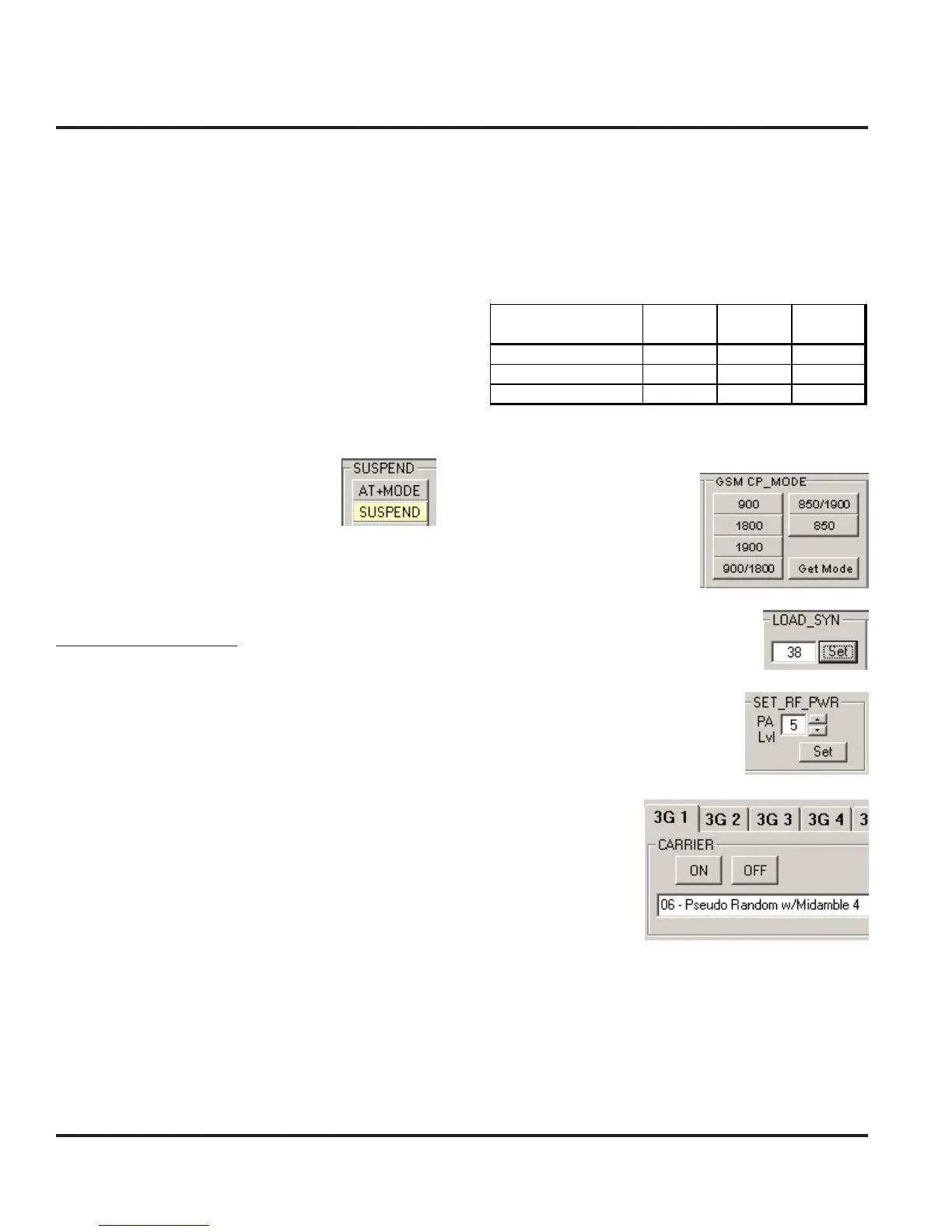
Verify TX Power Output (GSM/DCS/PCS)
Verify the TX Power output by initiating the commands
in this section. Verify that the results fall within the fol-
lowing limits.
Click on 900/1800 (GSM/
DCS) or 1900 (PCS)
Enter 38 (GSM), 700 (DCS), or 661
(PCS) and then click Set
Enter 5 (GSM) or 0 (DCS/PCS)
and then click Set
Select 06 and then
click ON
NOTE: Set Training Sequence to 4 on the test equip-
ment.
¹10*0*5 for PCS mode
²20*700*0 for DCS Channel 700; 20*661*0 for PCS Channel 661
³45*0 for DCS/PCS Power level 0
Table 2-6. TX Power Limits
Parameter
Low
Limit
High
Limit
Unit
GSM TX Power Out 31 33 dBm
DCS TX Power Out 28.2 30 dBm
PCS TX Power Out 28.2 30 dBm
Non-Signaling Test Procedures (GSM/DCS/PCS)
 Loading...