Motorola Confidential Proprietary
V975/V980Theory of Operation
3-16
Draft 1.0
lized for video conferencing – QCIF image size at up to
30fps. Support of VGA (680x480) resolution LCD at
16 and 18-bpp (with dithering) using only an embed-
ded frame buffer and up to 3MP cameras with resolu-
tions up to 2048x1536 image capture with a 10fps pre-
view and 2MP cameras with a 15fps preview. The video
processing engine is coupled with a JPEG encoder ca-
pable of encoding still images with 3MP resolution and
a JPEG decoder capable of playback motion JPEG at
up to 30fps at VGA resolution. The host interface bus
provides an 8, 16, or 32-bit asynchronous interface that
supports both direct and indirect addressing modes.
MMC/SD Flash Interface
The MMC/SD host controller provides an interface
between the POG and Triflash-R memory card.
The MMC/SD host controller handles MMC/SD pro-
tocol at transmission level, packing data, adding cyclic
redundancy check (CRC), start/end bit, and checking
for syntactical correctness.
Keypad Interface
The keypad provides the primary physical user inter-
face for the radio. The 5-way NAV joystick has a cen-
ter keypress in addition to the four primary directions.
White LED’s will be used for backlighting. The keypad
implementation to be used is the 2-contact, 1-pole key-
pad scanning architecture.
The Keypad Port (KPP) of POG decodes keypad
presses. The Keypad Port is a 16-bit peripheral which
is used for keypad matrix scanning. Keypad matrix uses
5 rows and 4 columns for key scanning. The KPP on
POG can support up to an 8 x 8 row-by-column key-
pad matrix. The KPP will use a 32.768 KHz clock.
The Power/End key will not be part of the matrix but
instead will connect directly to PCAP2.
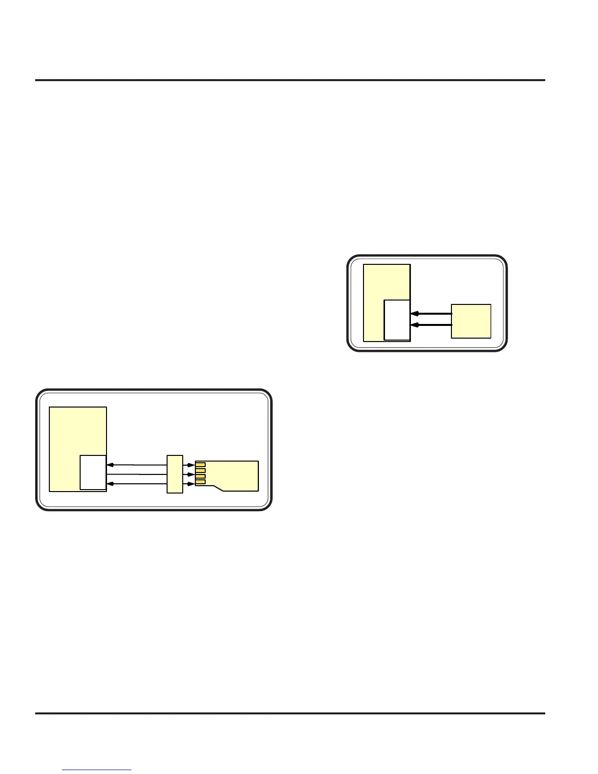
T-FLASH-R
MMC_CMD
MMC_CLK
MMC_DATO
MMC
I/F
J
3
9
0
1
POG
(U 1 000 )
Figure 3-20. MMC Interface
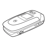
KYBD
I/F
KEY
BOARD
KBR(4:0)
KBC(5:0)
POG
(U10 00 )
Figure 3-21. Keyboard Interface
Baseband Electrical (Digital)
 Loading...