Motorola Confidential Proprietary
V975/V980Theory of Operation
3-4
Draft 1.0
RF GSM Receiver
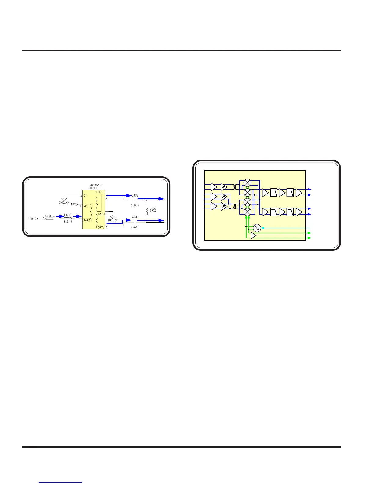
BALUN
From the FEM, the GSM singled-end, unbalanced re-
ceived signals are fed into the Algae MB section of the
Blue Module (900). Since the Algae MB expects a bal-
anced differential receive input signal, the EGSM, PCS,
and DCS signals must first pass through a differential
conversion. Balun transformers provide the conversions
from an unbalanced to a balanced line condition.
Each GSM band will contain a Balun transformer for
differential conversions. The expected insertion loss for
the Balun transformer is approximately 0.6 dBm.
BLUE MODULE IC (ALGAE)
Three LNAs are used for each receiver frequency band.
Two hi-band LNAs are used for DCS and PCS fre-
quencies and one low-band LNA is used for EGSM.
Both hi-band LNAs are grouped together to share the
same impedance matching transformer at the output.
The low-band EGSM LNAs uses a separate imped-
ance matching transformer at the the output.
Automatic gain control is provided by an AGC current
steering differential pair. This current steering stage di-
verts current from the LNA load to supply in order to
reduce the gain. The current steering differential pair
alone would not have the desired transfer function, there-
fore an AGC linearizer is needed to provide a response
that is linear in dB/V.
The LNAs drive AGC current steering stages that feed
integrated transformer matching networks. The trans-
former drives the quadrature mixers that convert the
RF signal to baseband quadrature I and Q.
The downmixer converts the RF signal to baseband so
that the signal can pass through a low-pass antialiasing
filter and be converted to a digital format.
The output of the mixer connects directly to the post-
Figure 3-4. Balun Transformer
GSM
DCS
PCS
AGCLNA
MIXER
ALGAE MB
(U900)
PMA
BB_O UT
IFF
AAFIFA
MB_RX_I
MB_RX_IX
MB_RX_Q
MB_RX_QX
RX VCO
RX_TUNE
SYNTH_FDBK
Figure 3-5. ALGAE MB (Receiver)
RF GSM Receiver
 Loading...