Motorola Confidential Proprietary
Theory of OperationService Manual(Level 3)
3-19
Draft 1.0
Audio Circuits
PCAP (U3000)
The PCAP2 IC is an ASIC intended for use in Colo-
rado platform mobile phones. It integrates several func-
tional modules:
• Voltage regulators of both linear and switching
types designed for use in the Colorado power
scheme
• Audio codecs and amplifiers
• RS-232 and USB transceivers
• LED controllers for the service light and dis-
play/keypad backlights
• Digital interfaces for two controlling processors.
TX Audio
The 3G termianl supports three microphone input paths
identified as Internal Microphone (AUX_MIC-), Head-
set Microphone (MICIN-), and External Microphone
(EXT_MIC). These three inputs are single-ended with
respect to VAG. The proper Microphone path is se-
lected by the MUX controller and path gain is pro-
grammable at the PGA.
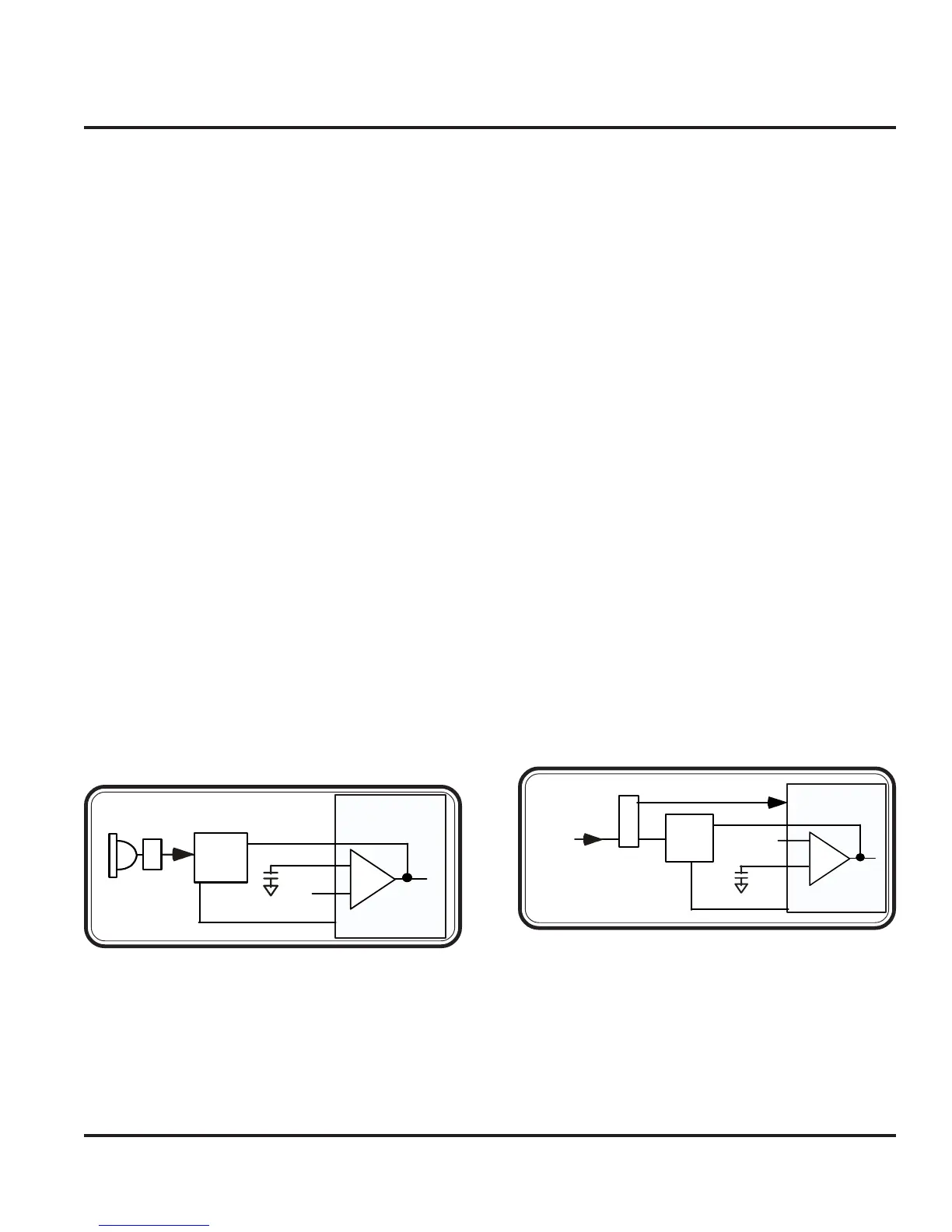
The Internal Microphone is a single ended through -
hole part. Following the Internal microphone path, the
microphone is biased by R4103 to provide a
MIC_BIAS of 2.0V from pin MIC_BIAS1 of PCAP.
C4198 is connected to MIC_BIAS1 and MB_CAP1
pin on PCAP to bypass the gain from the VAG to
MIC_BIAS1 which keeps the noise balanced. From
there, the signal is routed through C4100 and R4101 to
AUX_MIC- pin on PCAP, which is the input to the A5
amplifier. The microphone path is tapped off by R4102
to connect the AUX_OUT pin of PCAP, which is the
output of the A5 amplifier.
The headset microphone path is biased through R4396,
which is connected to pin MIC_BIAS2 on PCAP and
bypassed with C4199 connected to pin MB_CAP2.
From here the signal is routed through C4395 and R4388
to MIC_IN- pin on PCAP, which is the input to the A3
Amplifier. The Microphone path is tapped off after
R4388 before the MIC_IN- input to R4389 connected
to the MIC_OUT pin on PCAP, which is the output of
the A3 Amplifier. The HS_MAKE_DET line monitors
the presence of a headset by using R4399 as a pull-up
resistor and detecting the voltage at A1_INT of PCAP,
which passes through R4398. A switching mechanism
integrated in the headset jack will open or close the
HS_MAKE_DET path to ground, depending on
whether the headset is attached or not.
The External Microphone input is connected to the ac-
cessory connector for the mobile phone. The path is
routed through C4401 and R4401 to the EXT_MIC
pin on PCAP. This signal feeds directly to the input mul-
tiplexer without an intervening gain stage.
MIC_BIAS1
AUX_OUT
AUX_MIC-
Audio
Filter
Circuit
MIC
NC
J4100
A5
PCAP
Figure 3-25. Internal Mic Path
PCAP
MIC_BIAS2
MIC_OUT
Audio
Filter
Circuit
HS_MIC
J
4
3
0
0
A3
HS_MAKE_DETECT
NC
VAG
Figure 3-26. Headset Mic Path
Audio Circuits
 Loading...