Motorola Confidential Proprietary
Theory of OperationService Manual(Level 3)
3-21
Draft 1.0
The headset uses a standard 2.5mm stereo phone jack.
The phone will detect the presence of a stereo headset
using HS_SPKR_L of the headset jack, which is pulled
high by R4395 and connected to the ST_COMP of
PCAP (this is an interrupt of PCAP which gets sent to
MCU over the SPI bus). This pin will be pulled to a
logic low whenever the stereo headset plug is inserted
into the jack. The headset may contain a momentary
switch, which is normally closed and is in series with the
microphone cartridge. When the momentary switch is
pressed, the bias current being supplied to the micro-
phone will be interrupted. The phone will detect this
action and make an appropriate response to this ac-
tion, which could be to answer a call, end a call, or dial
the last number from scratchpad.
The Headset Speaker is driven by PCAP’s internal Left
and Right amplifier. Following the speaker path from
the PCAP pins ARight_Out and ALeft_Out, they are
routed through C4356, R34304 and C4306, R34303
respectively, and then connected to the headset jack.
Off the ARight _Out path, AR_IN is tapped off through
C4354 for the inverting input of the audio amp ARIGHT.
Off the ARight_Out path, AL_IN is tapped off through
C4354 for the inverting input of the audio amp ALEFT.
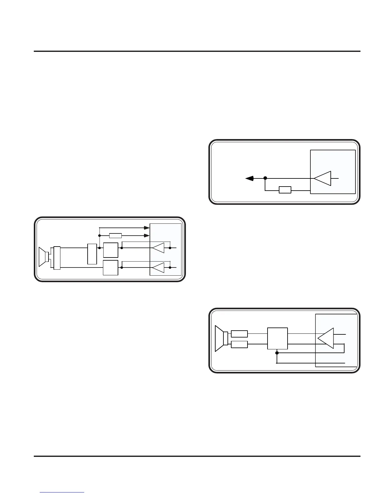
The External Speaker is connected to pin 15 of J5000
(AUDIO_OUT ON/OFF), the accessory connector
for the mobile phone. The audio path is routed through
R4400 and C4400 and connected to EXTOUT of
PCAP. The DC level of this Audio_Out signal is also
used to externally command the phone to toggle it’s
ON/OFF state. The Audio_Out signal connects to
PCAP’s ON2 pin via R5053 to provide this capability.
When a DC level of <0.4V is applied by an accessory
for a minimum of 700 milliseconds on the Audio_Out
line, the phone will toggle it’s ON/ OFF state.
The Alert Transducer is driven by PCAP’s ALRT am-
plifier (A2). The alert path from the PCAP pins ALRT-
and ALRT+ are routed directly to the alert transducer.
Off the ALRT- path, ALRT_IN is routed through R4201
for the inverting input of the alert amp A2. SPKROUT2
from PCAP is routed through C4200 and R4200 to
ALRT- which is the DAC output of the CODEC.
PCAP
ARIGHT_IN
ARIGHT_OUT
ALEFT_IN
ALEFT_OUT
Audio
Filter
Circuit
Audio
Filter
Circuit
HS_SPKR_L
HS_SPKR_R
ST_CMP
ST_REF
R4395
Stereo
Headset
J4300
FL4300
Figure 3-29. Headset Speaker Path
PCAP
EXTOUT
ON2
R5053
AUDIO_OUT
A4
Figure 3-30. External Speaker Path
PCAP
SPKROUT2
ALRT_IN
Audio
Filter
Circuit
ALRT-
ALRT+
Loudspeaker
J5501
J5500
A2
ALRT-
ALRT+
Figure 3-31. Alert Path
Audio Circuits
 Loading...