Motorola Confidential Proprietary
Theory of OperationService Manual(Level 3)
3-3
Draft 1.0
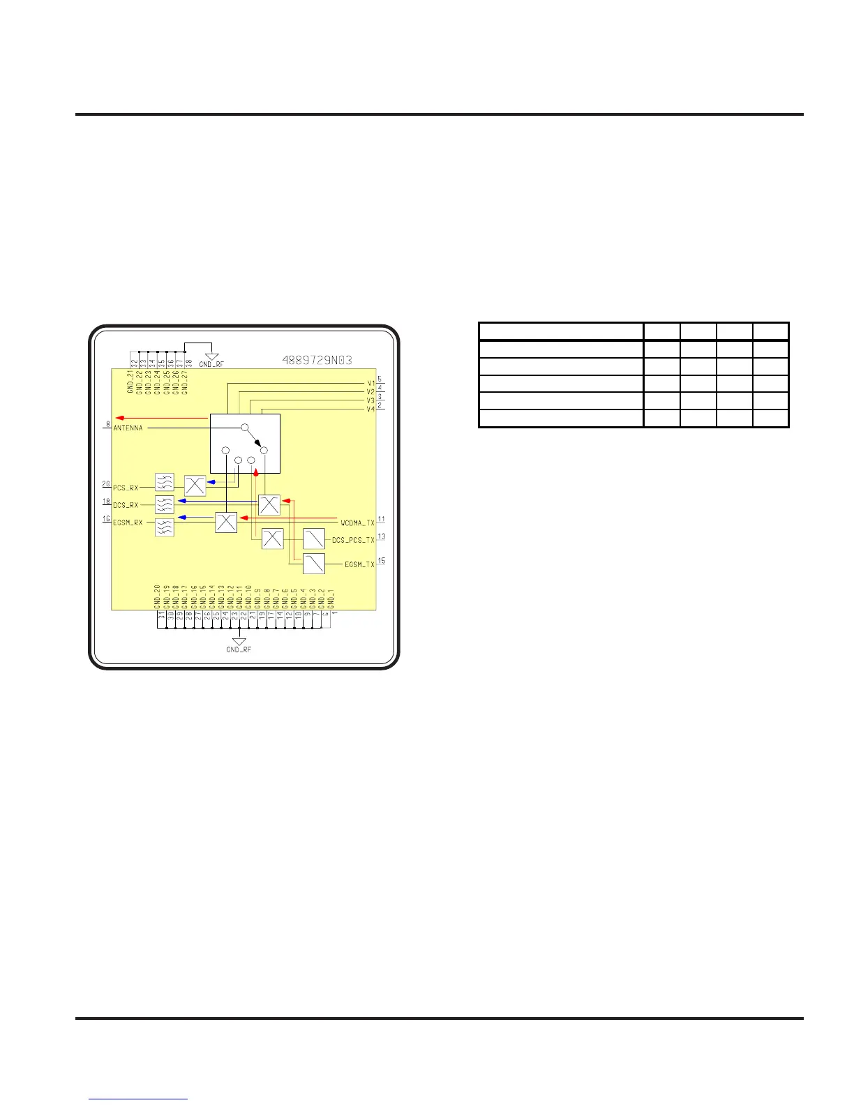
The FEM integrates a 4-position GaAs antenna switch,
diplexers, transmit harmonic filters, SAW filters and
matching components on a multilayer low-temperature
cofired ceramic (LTCC) module. The module provides
band selection and filtering between the EGSM, DCS,
PCS, and WCDMA (UMTS) receive and transmit
bands in the 3G terminal.
There is a network on each port of the antenna switch
that serves several functions. The primary function is to
make each switch path behave as an open circuit to
incoming signals in the WCDMA receive band (2110 –
2170 MHz). Signals in the WCDMA Rx band are
thereby reflected back to the WCDMA receiver. Re-
ceived signals in the EGSM, DCS or PCS bands are
allowed to pass through the switch and undergo some
pre-filtering, then pass through SAW filters before leav-
ing the module.
Signals from the WCDMA transmitter are diplexed with
EGSM Rx, sharing switch position 1. Similarly, signals
from the EGSM transmitter are diplexed with DCS Rx,
sharing switch position 4. Switch position 3 is used solely
by the DCS/PCS transmitter, and switch position 2 is
used only by PCS Rx.
Band Selection in the Front End Module follows the
Truth Table shown in table 3-1.
WCDMA Rx is available in any switch position.
Logic “1” is defined as 2.5 volts minimum.
Logic “0” is defined as 0 volts.
1
2
3
4
Harmo nic Filters
Ante nna Switch
GSM R X
SAW filters
Diplexing
Networks
Figure 3-3. FEM Module (FL001)
Band Selected
1
2
3
4
WCDMA Rx x x x x
WCDMA Tx, EGSM Rx 1000
PCS Rx 0100
DCS/PCS Tx 0010
EGSM Tx, DCS Rx 0001
Table 3-1. FEM Truth Table
Front End Module
 Loading...