Chapter 7: Ignition System
73
Ignition module
The ignition system is either a capacitive discharge or a
inductive discharge magneto, depending on the appli-
cation, contained in a single module.
• The capacitive discharge has a three leg design.
• The inductive discharge magneto has a two leg
design.
• The magneto is energized by the passing of a
pair of magnets mounted in the flywheel.
• Ignition timing is set by the location of the fly-
wheel in relation to the crankshaft. Proper timing
is maintained by a steel key.
NOTE: Regardless of which type of magneto is
used, the test procedures are the same.
Module removal
1. Unplug the spark plug.
2. Remove the recoil assembly by following the
steps described in Chapter 6: Starter.
3. Lift the fan shroud off of the three studs that
locate it. See Figure 7.23.
4. Unplug the wire from the spade terminal on the
module or unplug the insulated bullet connec-
tors, depending on the production date of the
engine.
5. Remove the module using a 10mm wrench.
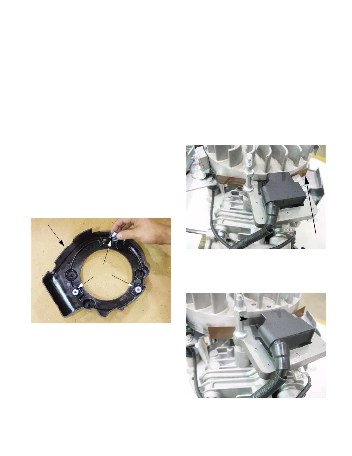
Figure 7.15
Fan shroud
Shoulder
bushings
Shoulder
bushings fit
over studs
Installing the module and setting the air gap
NOTE: If just setting the air gap, loosen the
module mounting screws first then follow the
same steps as described below.
1. Rotate the flywheel so that the magnets are
away from where the module is mounted.
2. Install the module. Do not tighten the module
down.
3. Place a non-ferrous feeler gauge between the
module and the flywheel. See Figure 7.16.
NOTE: The air gap should be .008”-.016” (.2-
.4mm).
4. Rotate the flywheel so that the magnets align
with the legs of the module while holding the
feeler gauge in place. See Figure 7.17.
Figure 7.16
.010” feeler
gauge
Figure 7.17
Magnet
www.mymowerparts.com
For Discount White Outdoor Parts Call 606-678-9623 or 606-561-4983
 Loading...