Chapter 7: Ignition System
75
5. Disconnect the connector in the lead that goes
to the module.
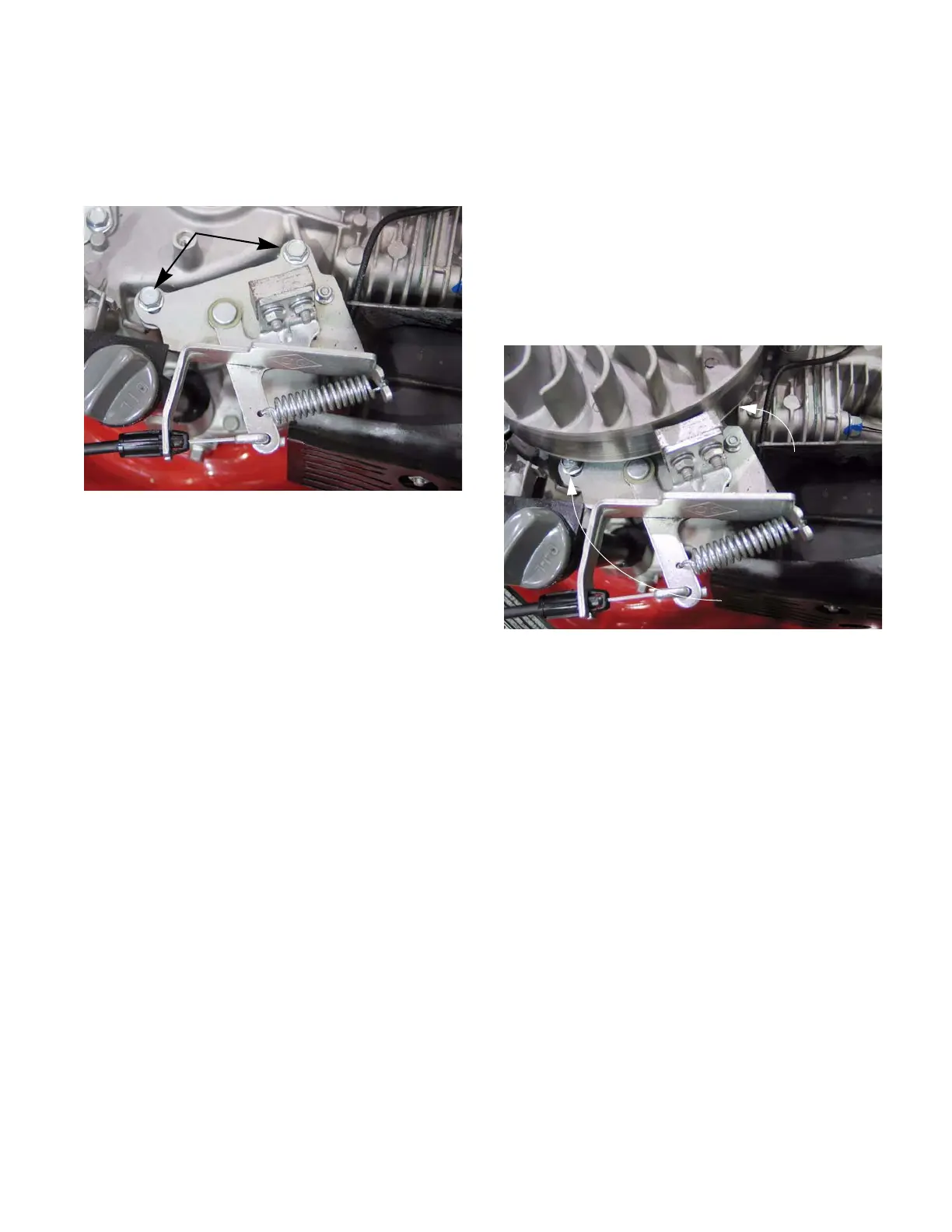
6. Remove the two bolts securing the brake
assembly. See Figure 7.19.
To install a brake assembly:
1. Set brake in place and loosely tighten the bolts.
2. Install the flywheel by following the steps
describe in a later section of he chapter.
3. Install the control cable.
4. Adjust the brake assembly by following the steps
described in the next section of this chapter.
5. Install the blower housing and recoil assembly
by following the steps described in Chapter 6:
Starter.
6. Test run the engine in a safe area before return-
ing it to service.
Figure 7.19
Remove these bolts
Adjusting the brake assembly (if equipped)
1. Disconnect and ground the spark plug wire.
2. Remove the recoil assembly and blower housing
by following the steps described in Chapter 6:
Starter.
3. Slightly loosen the two bolts that holds the brake
assembly in place using a 10mm wrench.
NOTE: The bolt near the cylinder is a pivot point
and the bolt by the dip stick is in a slot.
See Figure 7.20.
4. Use a spring clamp to hold the safety bail
against the upper handle bar.
Figure 7.20
Screw:
pivot point
Screw:
Adjustment
www.mymowerparts.com
For Discount White Outdoor Parts Call 606-678-9623 or 606-561-4983
 Loading...