Chapter 9: Cylinder Head
85
12. Carefully clean all sealing surfaces of all gasket
residue. Do not scratch the sealing surfaces.
NOTE: Make a visual inspection of the valves
and cylinder bore to confirm the initial diagnosis.
13. Place a new head gasket on the cylinder, allow-
ing the alignment dowels to hold it in place.
NOTE: Early production used siliconized head
gasket. Current production uses a graphite gas-
ket and it is a direct replacement for the older
head gasket. The graphite gasket is a one time
use only gasket and must be replaced any time
the cylinder head bolts are loosened.
14. Position the cylinder head on the engine block.
15. Install the 4 head bolts, and tighten them to a
step torque of 212 in-lb. (24 Nm) in an alternat-
ing diagonal pattern. See Figure 9.7.
NOTE: The bolt closest to the exhaust valve
must be the last bolt tightened. Failure to do so
will result in the head bolt loosening up.
16. Insert the push rods.
17. Install the rocker arms. Adjust the valve lash by
following the steps described in Chapter 1: Intro-
duction.
18. Install the carburetor and air cleaner, using new
gaskets, by following the steps described in
Chapter 3: Air Intake
19. Install the muffler by following the steps
described in Chapter 8: Exhaust.
20. Test run the mower in a safe area before return-
ing it to service. Check all safety features.
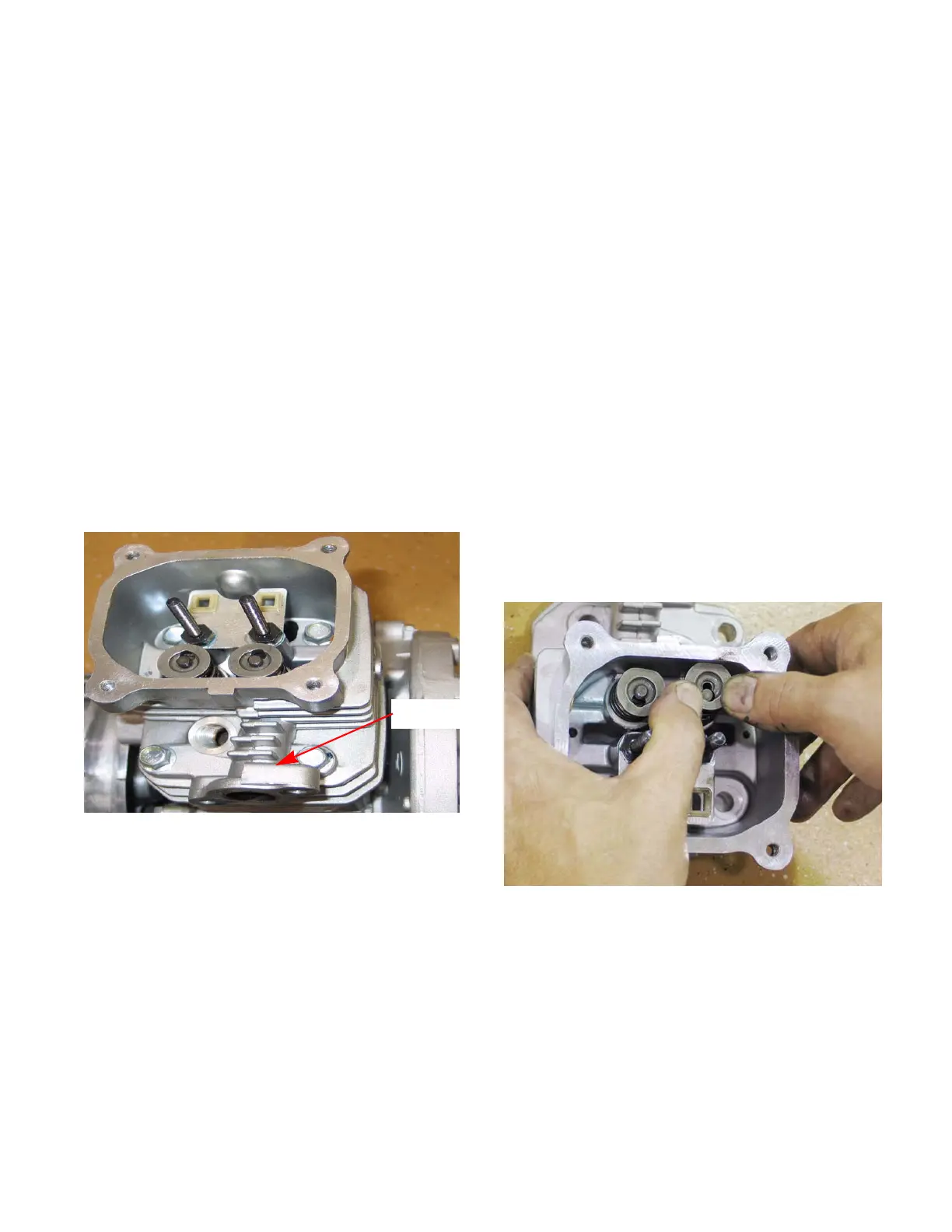
Figure 9.7
3
4
1
2
Exhaust
port
Valves
Valves and valve parts, like springs and keepers, are
not available as service parts. The valves and valve
seats can be serviced by grinding and lapping or the
head can be replaced. Depending on local machine
and labor costs, it is probably more economical to
replace the cylinder head versus servicing the valves.
To service the valves:
NOTE: Servicing valves during the warranty
period will void the warranty. Warranty valve
repairs are to be accomplished by replacing the
cylinder head.
1. Remove the cylinder head by following the steps
described earlier in this chapter.
2. Remove the rocker arms by:
2a. Remove the jam nuts.
2b. Remove the fulcrum nut.
2c. Slide the rocker arms off of the rocker studs.
3. Remove the valve retainers by applying light fin-
ger pressure on the valve retainers and sliding
them forward. See Figure 9.8.
4. Lift the springs off of the valve stems.
5. Slide the valves out of the cylinder head.
Figure 9.8
www.mymowerparts.com
For Discount White Outdoor Parts Call 606-678-9623 or 606-561-4983
 Loading...