Chapter 7: Ignition System
74
5. Tighten the module mounting screws to a torque
of 18.5 ft-lbs (10Nm).
6. Rotate the flywheel to remove the feeler gauge.
7. Install the blower housing and starter.
8. Connect the spark plug wire to the spark plug.
9. Test run the engine before returning to service.
Engine brake and stop switch (if equipped)
The stop switch and brake (for lawn mower applica-
tions) must be able to stop the blade from rotating
within 3.0 seconds after the release of the safety bail,
per ANSI B71.1-2003 standard.
NOTE: The brake should be replaced when the
thickness of the pad is less than .25” (6.35mm)
at the thinnest spot.
To replace the brake assembly:
1. Disconnect and ground the spark plug wire.
2. Remove the recoil assembly and blower housing
by following the steps described in Chapter 6:
Starter.
3. Remove the flywheel by following the steps
described later in this chapter.
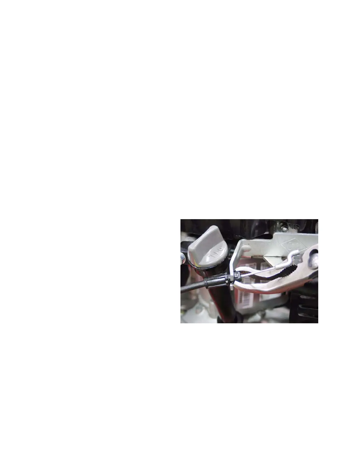
4. Remove the engine control cable by:
4a. Squeeze the barbs together at the engine
end of the cable housing and push it
through the brake assembly.
4b. Unhook the Z-fitting from the brake assem-
bly. See Figure 7.18.
Figure 7.18
Releasing the engine control
cable from the bracket
www.mymowerparts.com
For Discount White Outdoor Parts Call 606-678-9623 or 606-561-4983
 Loading...