2205B0JE-DA-J-N_2014.05.
5 Maintenance and Inspection
Screw Compressor J-series 5.4 Disassembly and Assembly of the Compressor
5-31
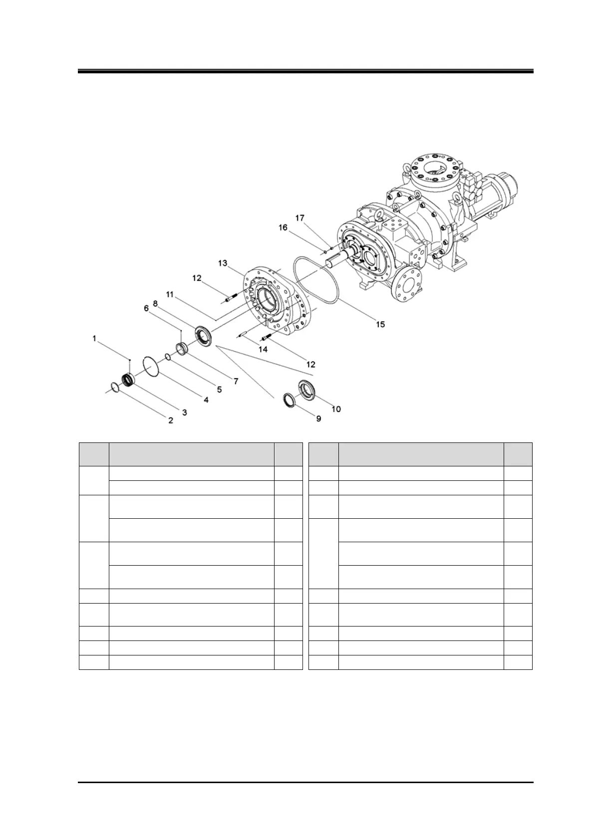
5.4.9 Bearing Cover
170J/220J/280J
Order Description
Part
No.
Order Description
Part
No.
1
Mechanical seal assembly 100 9 Oil seal 50
Hexagon socket set screw 100-5 10 Retainer for oil seal 48
2
Mechanical seal assembly 100 11
Spring pin
(3 dia.×8/3 dia.×10/3 dia.×10)
20
O-ring 100-4
12
Hexagon socket head cap screw
(280J: M20×50)
18
3
Mechanical seal assembly 100
Hexagon socket head cap screw
(M12×50/M16×60)
18-1
Rotating ring 100-3
Hexagon socket head cap screw
(M12×70/M16×90)
18-2
4 O-ring (G120/G145/G165) 49 13 Bearing cover 16
5 O-ring (G55/G70/G90) 744 14
Parallel pin
(10 dia. ×55/13 dia. ×65/16 dia. ×70)
19
6 Hexagon socket set screw (M6×8) 529 15 O-ring (P300/P375/P480) 17-1
7 Sleeve, oil seal 528 16 O-ring (P14) 17-2
8 Retainer for oil seal — Bush, P14 type O-ring 537
1. Remove the parts in the order of the numbers shown in the figure.
2. Install the parts in the reverse order of removing.
 Loading...


