2205B0JE-DA-J-N_2014.05.
5 Maintenance and Inspection
Screw Compressor J-series 5.4 Disassembly and Assembly of the Compressor
5-62
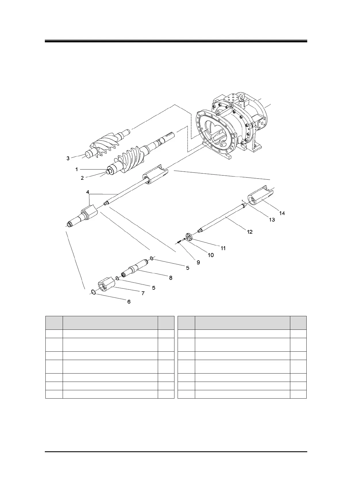
5.4.19 Rotors
170J/220J/280J
Order Description
Part
No.
Order Description
Part
No.
1 Key for balance piston 31 8 Push rod, Vi 292
2 Male rotor 25 9
Hexagon socket head cap screw
(M8×30/M8×35/M10×40)
58
3 Female rotor 26 10 Spring lock washer (M8/M8/M10) 267
4
Unloader slide valve assembly and
slide valve assembly, Vi
—11
Gland, push rod for unloader slide
valve
451
5 O-ring (P32) 325-1 12 Unloader push rod 67
6 Spiral retaining ring 293 13 Grooved pin 446
7 Slide valve, Vi 289 14 Unloader slide valve 54
1. Remove the parts in the order of the numbers shown in the figure.
2. Install the parts in the reverse order of removing.
 Loading...


