EasyManuals Logo
Home>mycom>Air Compressor>J Series

mycom J Series User Manual

Default Icon
209 pages
To Next Page IconTo Next Page
To Previous Page IconTo Previous Page
Page #132 background imageLoading...
Page #132 background image
2205B0JE-DA-J-N_2014.05.
5 Maintenance and Inspection
Screw Compressor J-series 5.4 Disassembly and Assembly of the Compressor
5-58
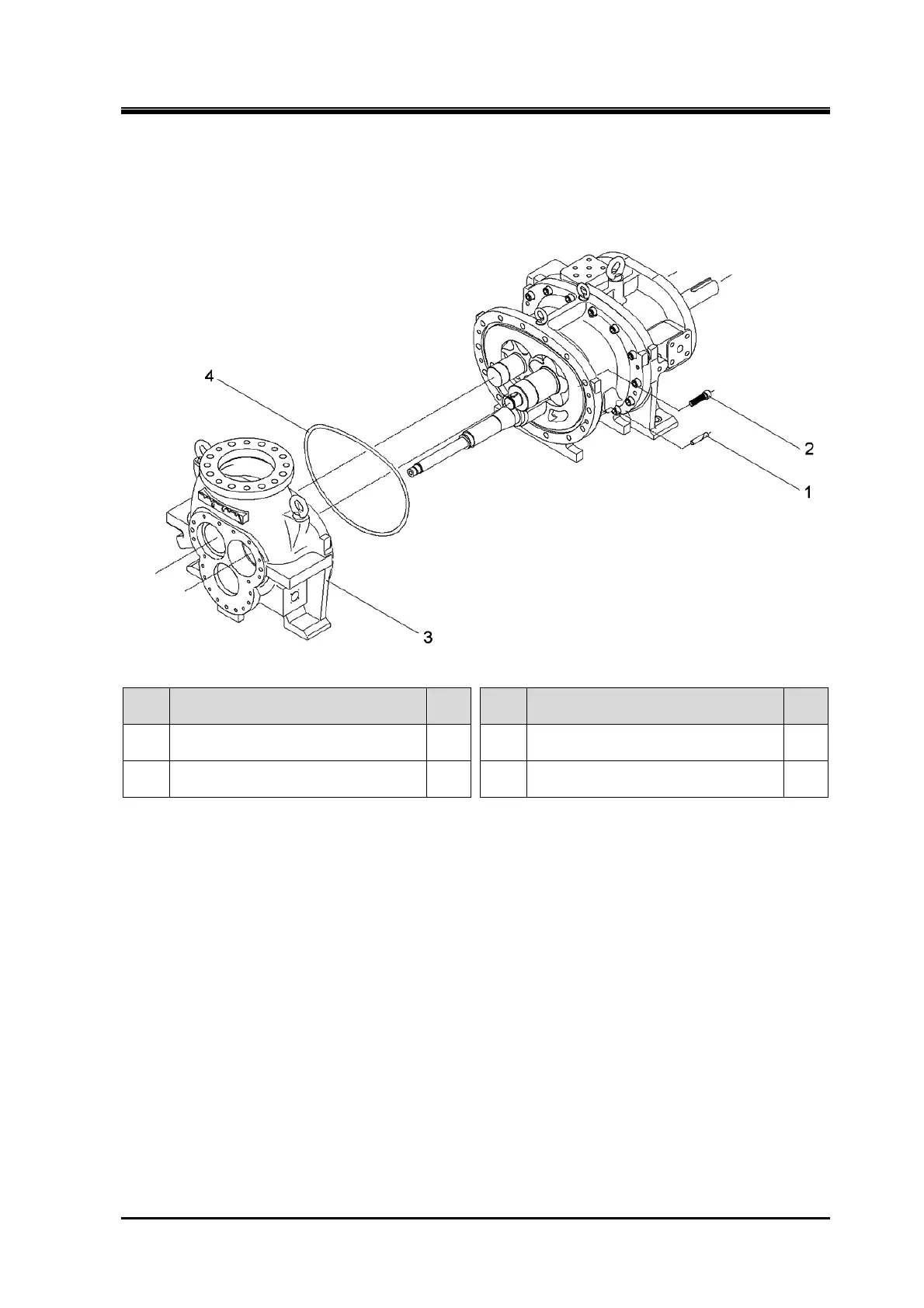
5.4.17 Separation of Suction Cover and Main Rotor Casing
170J/220J/280J
Order Description
Part
No.
Order Description
Part
No.
1
Parallel pin
(13 dia.×65/13 dia.×65/16 dia.×110)
3 3 Suction cover 5
2
Hexagon socket head cap screw
(M16×60/M16×75/M20×110)
2 4 O-ring (P375/P450/P580) 6
1. Remove the parts in the order of the numbers shown in the figure.
2. Install the parts in the reverse order of removing.

Table of Contents

Other manuals for mycom J Series

Questions and Answers:

Question and Answer IconNeed help?

Do you have a question about the mycom J Series and is the answer not in the manual?

mycom J Series Specifications

General IconGeneral
Brandmycom
ModelJ Series
CategoryAir Compressor
LanguageEnglish

Related product manuals