2205B0JE-DA-J-N_2014.05.
5 Maintenance and Inspection
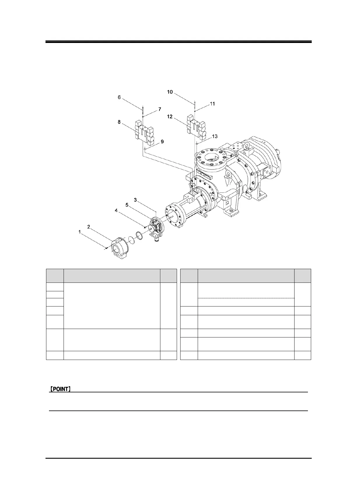
Screw Compressor J-series 5.4 Disassembly and Assembly of the Compressor
5-34
5.4.10 Unloader Indicator/Capacity Control Solenoid Valve
170J/220J
Order Description
Part
No.
Order Description
Part
No.
1
Assembly, unloader indicator 120
8
Capacity control / variable Vi
solenoid valve
562
2
3 or Solenoid valve dummy block
4 9 O-ring 561
5 10
Hexagon socket head cap screw
(M5×75)
535
6
Hexagon socket head cap screw
(M5×75)
535
11 Spring lock washer 536
12
Capacity control / variable Vi
solenoid valve
562
7 Spring lock washer 536 13 O-ring 561
1. Remove the parts in the order of the numbers shown in the figure.
2. Install the parts in the reverse order of removing.
Make sure to remove all drain plugs and don’t cover the outlet of oil and the inlet of oil for
hydraulic cylinder before removing the solenoid valve.
NOTE:
According to the design modification notification as of January 2014, J series unloader indicators have
all changed to explosion-proof type which is newly designed. For details of this new unloader indicators
refer to their instruction manual provided separately.
 Loading...


