2205B0JE-DA-J-N_2014.05.
5 Maintenance and Inspection
Screw Compressor J-series 5.4 Disassembly and Assembly of the Compressor
5-39
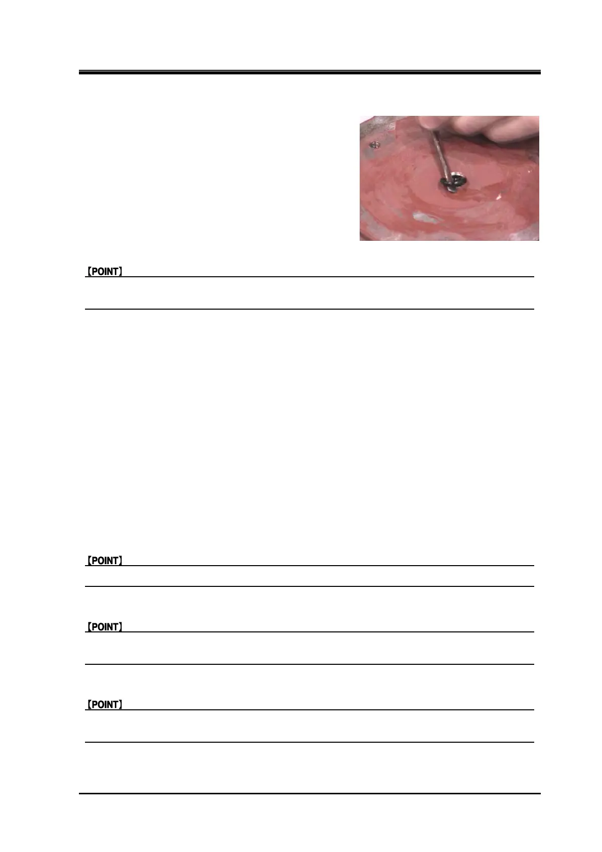
O-ring (P10A)
1.
If the O-ring remains on the unloader cylinder
cover, remove it by using an appropriate tool (2—3
mm dia. wire with a flat point).
Locknut (FU nut) (only for 170J)
The FU nut has a high friction locking device. Turn the FU nut with a locknut wrench until it is
loosened.
Unloader piston
1.
Using eyebolts (M8), remove the unloader piston from the unloader push rod.
5.4.11.3 Precautions for Installation
Unloader piston
1.
Attach the O-ring (P130/P170/P225) to the unloader piston.
2. Attach the Teflon cap seal to the outside of the O-ring.
3. Using eyebolts (M8), put the unloader piston into the unloader cylinder and install the unloader
piston to the unloader push rod.
O-ring (P130/P170/P225)
Do not apply silicon grease to the O-ring (P130/P170/P225) of the unloader piston.
Teflon cap seal
Attach the Teflon cap seal to cover the outside of the O-ring. Make sure both sides of the Teflon
cap seal do not stick out of the O-ring groove on the unloader piston.
Push rod
Pull the push rod towards yourself so that the push rod can be inserted into the internal face of
the unloader piston, before inserting the unloader piston into the unloader cylinder.
 Loading...


