2205B0JE-DA-J-N_2014.05.
5 Maintenance and Inspection
Screw Compressor J-series 5.4 Disassembly and Assembly of the Compressor
5-40
O-ring (P10A)
1.
Assemble the O-ring (P10A) to the inside of the O-ring retainer in advance.
O-ring retainer
1.
Attach two O-rings (P10A) to the inner face of the O-ring retainer and one O-ring (P16) to the
outer face, and install the O-ring retainer to the unloader cylinder cover.
Unloader cylinder cover spacer
1.
Install the unloader cylinder cover spacer to the
unloader cylinder cover with the flat face to the
atmosphere side.
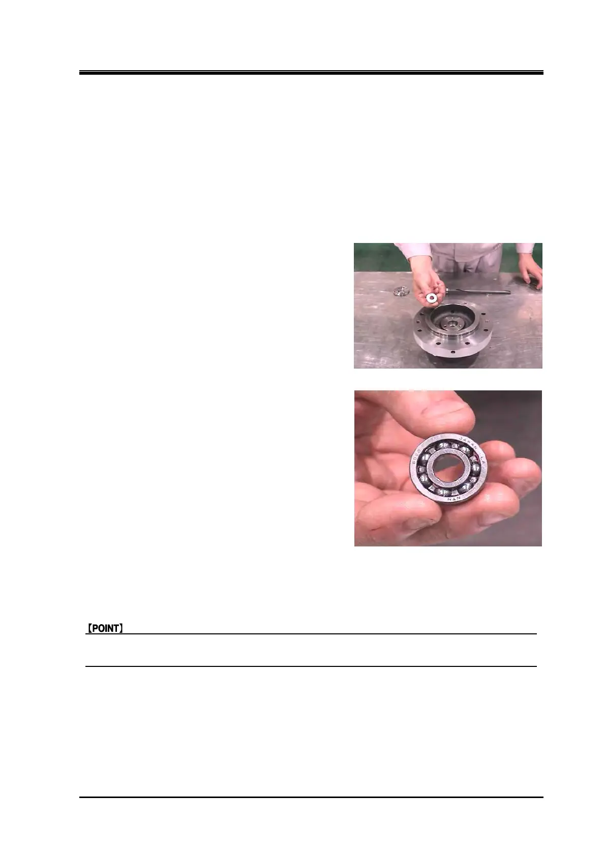
Unloader indicator cam assembly
1.
Install the ball bearing to the cam shaft, with the
surface with stamped letters (mfg codes) of the ball
bearing facing the suction cover side.
2. Attach the retaining ring C type external (S10).
3. Install the unloader indicator cam with the ball
bearing to the unloader cover.
Bearing gland
1.
Install the bearing gland so that it contacts the ball bearing of the unloader indicator cam.
Locknut (FU nut) (only for 170J)
The FU nut has a high friction locking device. Turn the FU nut with a locknut wrench when
tightening the FU nut.
 Loading...


