2205B0JE-DA-J-N_2014.05.
5 Maintenance and Inspection
Screw Compressor J-series 5.4 Disassembly and Assembly of the Compressor
5-54
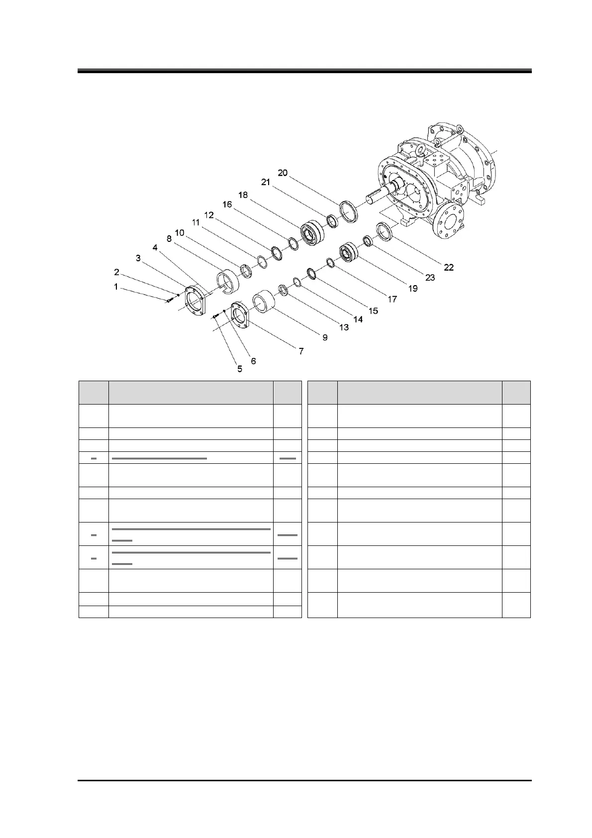
5.4.16 Thrust Bearings
170J
Order Description
Part
No.
Order Description
Part
No.
1
Hexagon socket head cap screw
(M8×30)
45 13 Locknut (AN09) 39-2
2 Spring lock washer 46 14 Torsional slip washer (125) 237-2
3 Thrust bearing gland, male rotor 43-1 15 Lock washer (AW09) 40-2
4 Spring pin (3 dia.×10) 729 16 Thrust washer, male rotor 250-1
5
Hexagon socket head cap screw
(M8×30)
45 17 Thrust washer, female rotor 250-2
6 Conical spring washer 46 18 Thrust bearing assembly, male rotor 38-1
7 Thrust bearing gland, female rotor 43-2 19
Thrust bearing assembly, female
rotor
38-2
8
Thrust bearing gland spacer, male
rotor
44
-1 20
Thrust bearing outer race spacer,
male rotor
41-1
9
Thrust bearing gland spacer, female
rotor
44
-2 21
Thrust bearing alignment spacer,
male rotor
42-1
10 Locknut (AN12) 39-1 22
Thrust bearing outer race spacer,
female rotor
41-2
11 Torsional slip washer (160) 237-1
23
Thrust bearing alignment spacer,
female rotor
42-2
12 Lock washer (AW12) 40-1
1. Remove the parts in the order of the numbers shown in the figure.
2. Install the parts in the reverse order of removing.
Note:
According to design modification notification as of March 29, 2012, thrust bearing grand spacer and
trust bearing gland have been integrated. Accordingly the parts indicated with double strikethrough on
the parts list on this page and the following page have been discontinued.
As for the serial number and other detailed information of the compressor applied for this design
modification refer to clause 7.4 design modification information (No.C0957-00) in chapter 7. If you
require information about the bearing head before this design modification, refer to the instruction
manual (No.2202B0-JJ-DA-J-N_2012.01.).
 Loading...


