2205B0JE-DA-J-N_2014.05.
5 Maintenance and Inspection
Screw Compressor J-series 5.4 Disassembly and Assembly of the Compressor
5-27
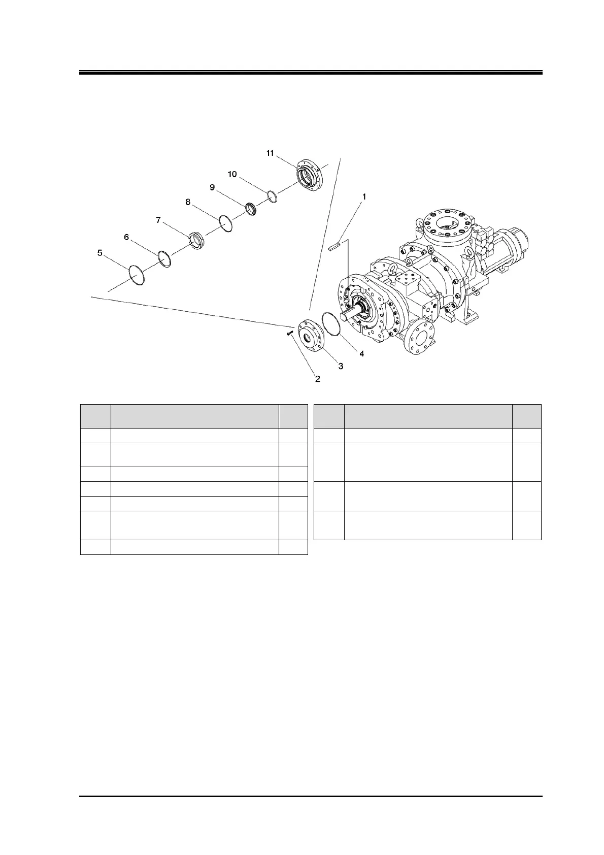
5.4.8 Seal Cover
170J
Order Description
Part
No.
Order Description
Part
No.
1 Shaft key 91 8 O-ring (G100) 657
2
Hexagon socket head cap screw
(M8×30)
53
9
Mechanical seal assembly
Mating ring
100
100-2
3 Seal cover assembly —
4 O-ring (G145) 52-2
10
Mechanical seal assembly
O-ring
100
100-1
5 O-ring (G120) 52-1
6
Retaining ring C type internal
(H100)
658 11 Seal cover
51
7 Sleeve, shower flushing 611
1. Remove the parts in the order of numbers shown in the figure.
2. Install the parts in the reverse order of removing.
 Loading...


