2205B0JE-DA-J-N_2014.05.
5 Maintenance and Inspection
Screw Compressor J-series 5.4 Disassembly and Assembly of the Compressor
5-48
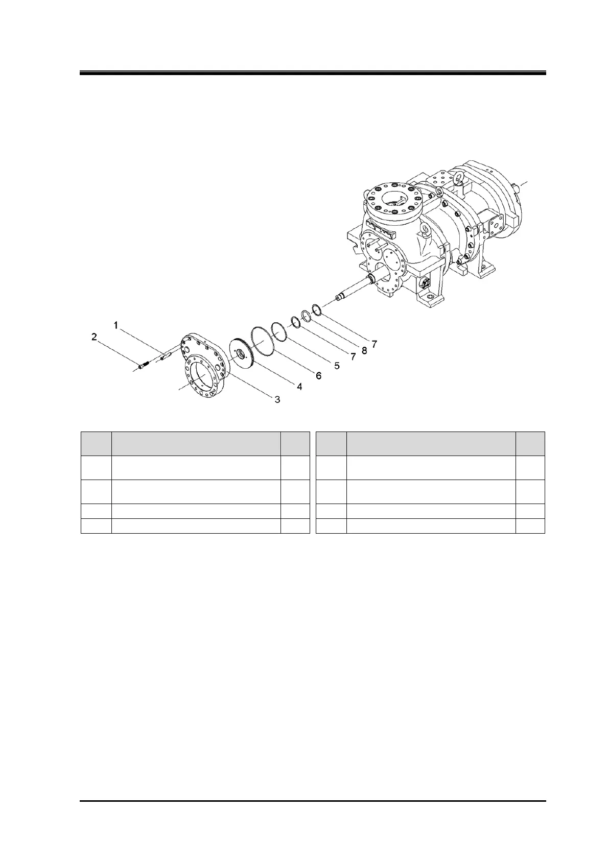
5.4.14 Balance Piston Cover
170J/220J/280J
Order Description
Part
No.
Order Description
Part
No.
1
Parallel pin
(10 dia.×55/16 dia.×55/16 dia.×70)
591 5 O-ring (G100/G100/G135) 299-1
2
Hexagon socket head cap screw
(M12×50/ M16×60/ M20×70)
24 6 O-ring (WG36/G200/G260) 299-2
3 Balance piston cover 22 7 Back-up ring for O-ring 9-2
4 Partition plate, suction cover 736 8 O-ring (P52/P65/P85) 9-1
1. Remove the parts in the order of the numbers shown in the figure.
2. Install the parts in the reverse order of removing.
 Loading...


