2205B0JE-DA-J-N_2014.05.
5 Maintenance and Inspection
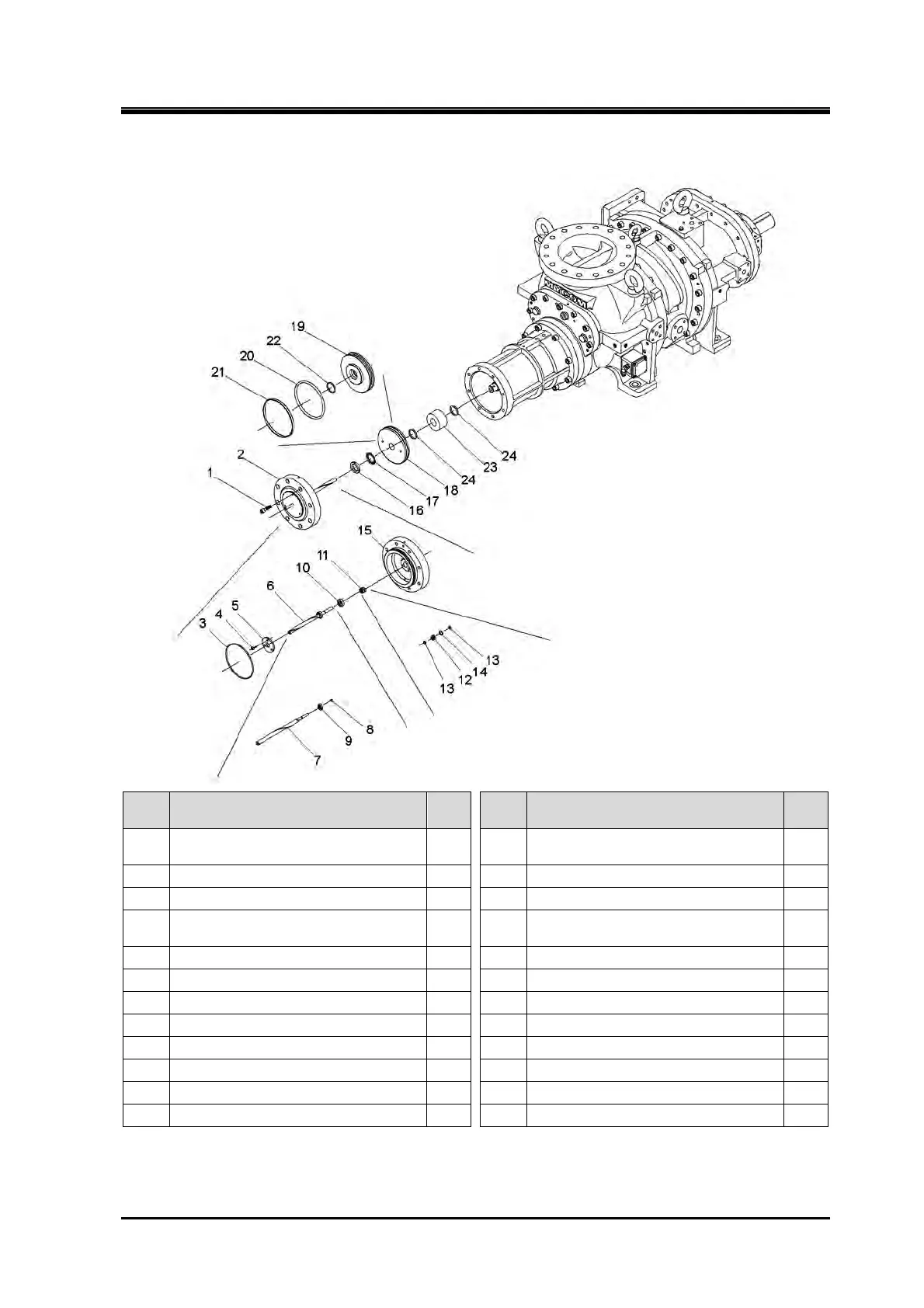
Screw Compressor J-series 5.4 Disassembly and Assembly of the Compressor
5-37
280J
Order Description
Part
No.
Order Description
Part
No.
1
Hexagon socket head cap screw
(M16×60)
76 13 O-ring (P10A) 82-1
2 Unloader cylinder cover assembly — 14 O-ring (P16) 82-2
3 O-ring (G230) (280J) 75 15 Unloader cylinder cover 74
4
Hexagon socket head cap screw
(M6×15)
81 16 Locknut (AN09) 69
5 Bearing gland 80 17 Lock washer (AW09) 70
6 Unloader indicator cam assembly — 18 Unloader piston assembly —
7 Unloader indicator cam 77 19 Unloader piston 64
8 Retaining ring C type external (S10) 79 20 O-ring (P225) 65
9 Ball bearing 78 21 Teflon cap seal (SUNR-BE-225) 66
10 Spacer, unloader cover 84 22 O-ring (P58) 73
11 Retainer assembly, O-ring — 23 Unloader spacer 420
12 Retainer, O-ring 83 24 O-ring (P58) 421
1. Remove the parts in the order of the numbers shown in the figure.
2. Install the parts in the reverse order of removing.
 Loading...


