2205B0JE-DA-J-N_2014.05.
5 Maintenance and Inspection
Screw Compressor J-series 5.4 Disassembly and Assembly of the Compressor
5-51
220J/280J
Order Description
Part
No.
Order Description
Part
No.
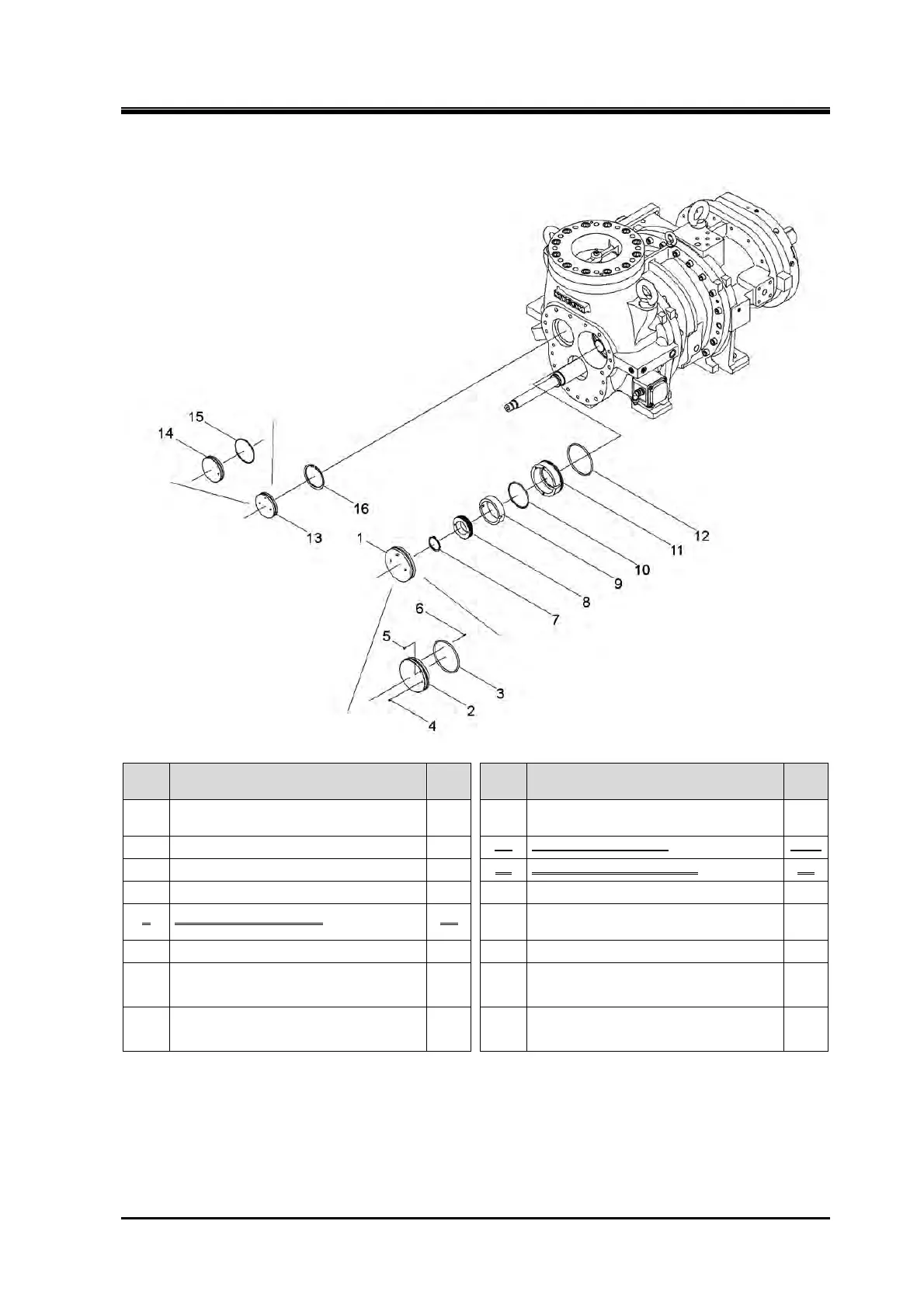
1
Inner cover M assembly, balance
piston cover
— 9 Sleeve, balance piston 33
2 Inner cover M, balance piston cover 734-1 10 O-ring (P120/G150) 35-1
3 O-ring (G150/G190) 23-1 11 Housing, balance piston 36
4 Spring pin (6 dia.×12) 34 12 O-ring (G150/G190) 35-2
5 Spring pin (6 dia.×12) 34 13
Inner cover F assembly, balance
piston cover
—
6 Spring pin (6 dia.×12) 34 14 Inner cover F, balance piston cover 734-2
7
Retaining ring C type external
(S65/S80)
32 15 O-ring (G115/G150) 23-2
8 Balance piston 30 16
Retaining ring C type internal
(H120/None)
37
1. Remove the parts in the order of the numbers shown in the figure.
2. Install the parts in the reverse order of removing.
 Loading...


