2205B0JE-DA-J-N_2014.05.
5 Maintenance and Inspection
Screw Compressor J-series 5.4 Disassembly and Assembly of the Compressor
5-74
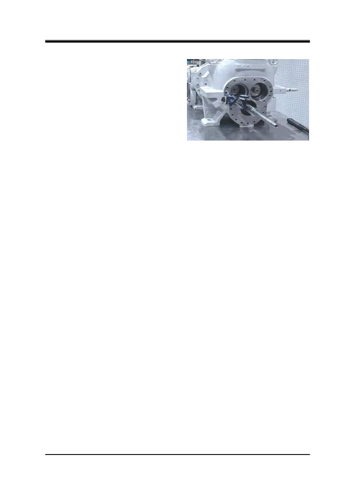
8. Press the end face of female rotor on suction
side securely.
9. Attach the point of a dial gauge to the
suction cover-side end face of the female
rotor.
10. Reset the dial gauge scale to 0.
11. Using a torque wrench, tighten the
hexagon socket head cap screws
(M8×30/M12×50/M16×65) for thrust gland
diagonally little by little and finally tighten
them to the specified torque.
12. Check if the dial gauge reads the specified
range.
Specified range : 0.04 - 0.06 (170J)
0.06 - 0.08 (220J)
0.10 - 0.14 (280J)
(1) When the end clearance is smaller than the specified value
To deal with this, insert shim material (thrust adjustment liner) of required thickness (difference
in thickness from the specified value) between the thrust bearing alignment spacer 【42】 and
thrust bearing inner race.
* The thrust adjustment liner is not shown in the development view, but available from us. Place
an order together with a model name.
Also, in case of 170 J and the 220 J series, using a highly accurate surface grinding machine
or asking professional service vendors to grind, grind the surface of thrust bearing outer race
spacer【41】 by the difference from the specified value. This method doesn't apply to the 280 J
series which isn't using a thrust bearing outer race spacer.
After grinding the flat surface, measure the whole circumference of the saucer by using a
micrometer, and check that the thickness is even.
(2) When the end clearance is larger than the specified value
As the end clearance is excessive, remove shim material (thrust adjustment liner) of a
thickness equal to the difference between the measured value and the specified value if the
shim material is used between thrust bearing alignment spacer and thrust bearing inner race.
Or if the shim material is not used between thrust bearing alignment spacer and thrust bearing
inner race, or even if used but insufficient thickness, grind the surface of thrust bearing
alignment spacer【42】 by the difference between the measured value and the specified value
or ask professional service vendors to do so. This method applies to the 170J series and 220J
series.
After grinding the flat surface, measure the whole circumference of the spacer by using a
micrometer, and check that the thickness is even.
13. After finishing end clearance adjustment, remove one of the hexagon socket head cap screw
(M8×30/M12×50/M16×65) of the thrust bearing gland for the male rotor, attach a spring lock
washer to the hexagon socket head cap screw, and then reattach and tighten the hexagon socket
head cap screw to the specified torque.
14. Repeat this work for all hexagon socket head cap screws (M8×30/M12×50/M16×65) of the thrust
bearing gland for the male rotor in a star pattern.
15. Perform the same operation to the hexagon socket head cap screws (M8×30/M12×50/M16×65) of
the thrust bearing gland for the female rotor.
 Loading...


