2205B0JE-DA-J-N_2014.05.
2 Structure and Specifications of the Compressor
Screw Compressor J-series 2.3 Compressor Specifications
2-13
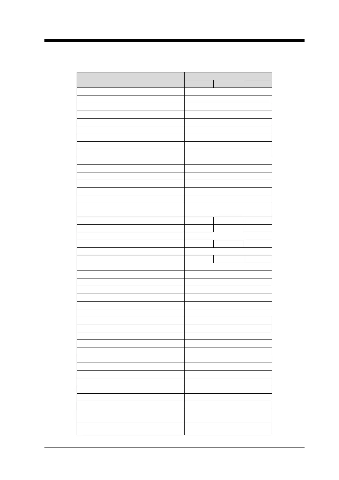
Table 2-8 Outer Dimensions of the 280J-series
Unit: mm
Item
280J
S M L
1:Suction ANSI #300 12”(16-M30)
2:Discharge ANSI #300 8”(12-M22)
3:Oil supply (Discharge-side) ANSI #300 1”(4-M16)
4:Oil supply (Suction-side) ANSI #300 3/4”(4-M16)
5:Oil injection ANSI #300 1 1/4”(4-M16)
6:E-port ANSI #300 2 1/2”(8-M20)
7:I-port ANSI #300 1”(4-M16)
8:F-injection (Option)
Rc1 1/4
9-1:Capacity control increase Rc1/2
9-2:Capacity control decrease Rc1/2
10-1:Vi control increase(L→H) Rc1/2
10-2:Vi control decrease(H→L) Rc1/2
11:Capacity control oil return Rc1/2
12:Unloader indicator connect PF 3/4
13:Vi-sensor connect connector
14:The leg hole for securing the
compressor
4-φ33
L1 2112 2205 2328
L2 562 655 778
L3 247
L4 460 553 676
L5 186
L6 517 610 733
L7 624
L8 90
L9 130
L10 158
L11 140
H1 780
H2 400
H3 205
H4 680
H5 481
H6 195
H7 90
W1 896
W2 320
W3 640
W4 440
W5 355
W6 112(M rotor side)
W7 108
W8 25
0
-0.052
D1 85
+0.011
-0.011
 Loading...


