2-2 | ni.com
Chapter 2 Digital I/O
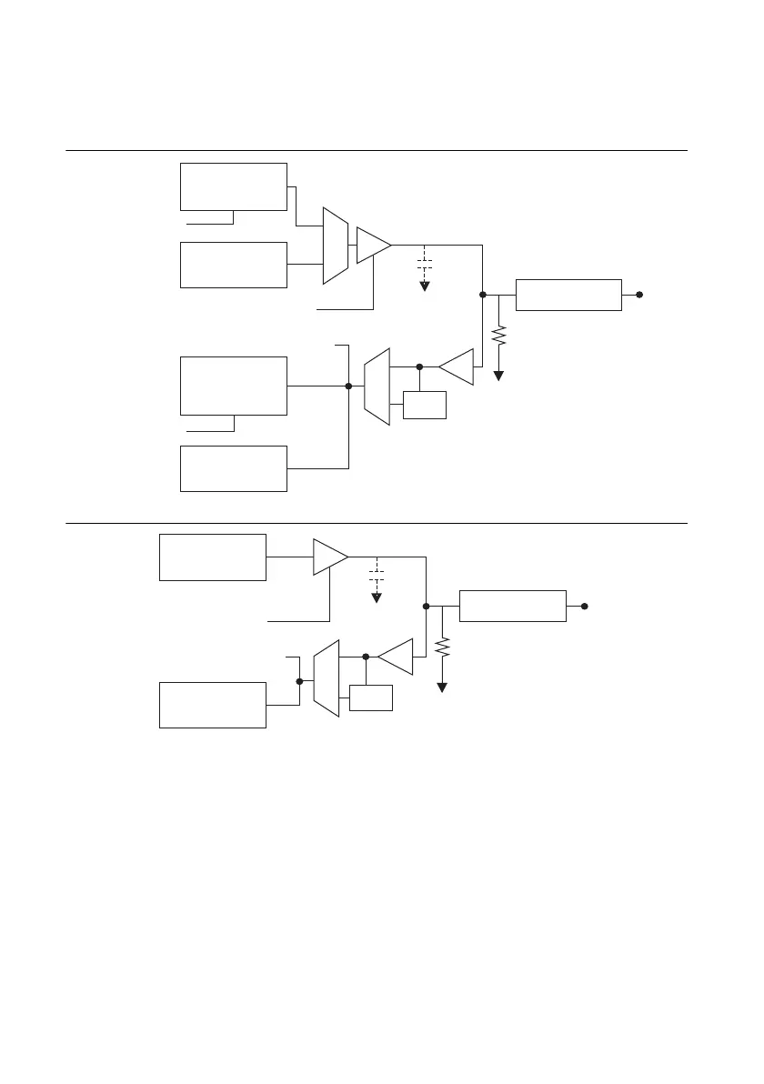
Figures 2-1 and 2-2 show the circuitry of a DIO line on Port 0 and Port 1 respectively. Each DIO
line is similar.
Figure 2-1. Digital I/O Circuitry on Port 0
Figure 2-2. Digital I/O Circuitry on Port 1
In both Figures 2-1 and 2-2, CI represents additional input capacitance. This capacitance
provides some filtering and slew-rate control benefits. However, the capacitance also limits the
maximum input frequency.
CI is populated on all the lines except for the default counter source input pins. CI is not
populated on the default source input pins in order to allow the measurement of higher speed
input signals. Table 2-2 lists the lines that do not populate CI. You must use the lines in Table 2-2
when measuring inputs frequencies above 25 MHz. For more information, refer to the NI 6612
Specifications.
DO Sample Clock
DO Waveform
Generation FIFO
DO.x Direction Control
Static DI
DI Sample Clock
DI Change
Detection
I/O Protection
Weak Pull-Down
P0.
Static DO
Buffer
DI Waveform
Measurement
FIFO
Filter
CI
DO.x Direction Control
Static DI
DI Change
Detection
I/O Protection
Weak Pull-Down
P1.
x
Static DO
Buffer
Filter
CI
 Loading...


