© National Instruments | 3-19
NI 6612 User Manual
By default, the counters measure the frequency on a default PFI terminal (refer to Chapter 5,
Counter Signal Routing and Clock Generation, for more information) and use an onboard
100 MHz clock as the timebase. To change the signals used for this measurement, configure the
following:
• CI.Freq.Term—The signal-to-measure comes from an input terminal. To change the
signal-to-measure, set this property to a different terminal.
• CI.CtrTimebase.Src—To change the signals used as the counter timebase, set this
property to a different terminal.
Period Measurement
Period measurements return the inverse result of Frequency measurements. Refer to the
Frequency Measurement section for more information.
The settings available for Period measurements are similar to Frequency measurements. For
example, use CI.Period.Term to change the signal-to-measure.
Pulse-Width Measurement
Note This section describes Pulse-Width measurements. For Pulse measurements,
refer to the
Pulse Measurement section.
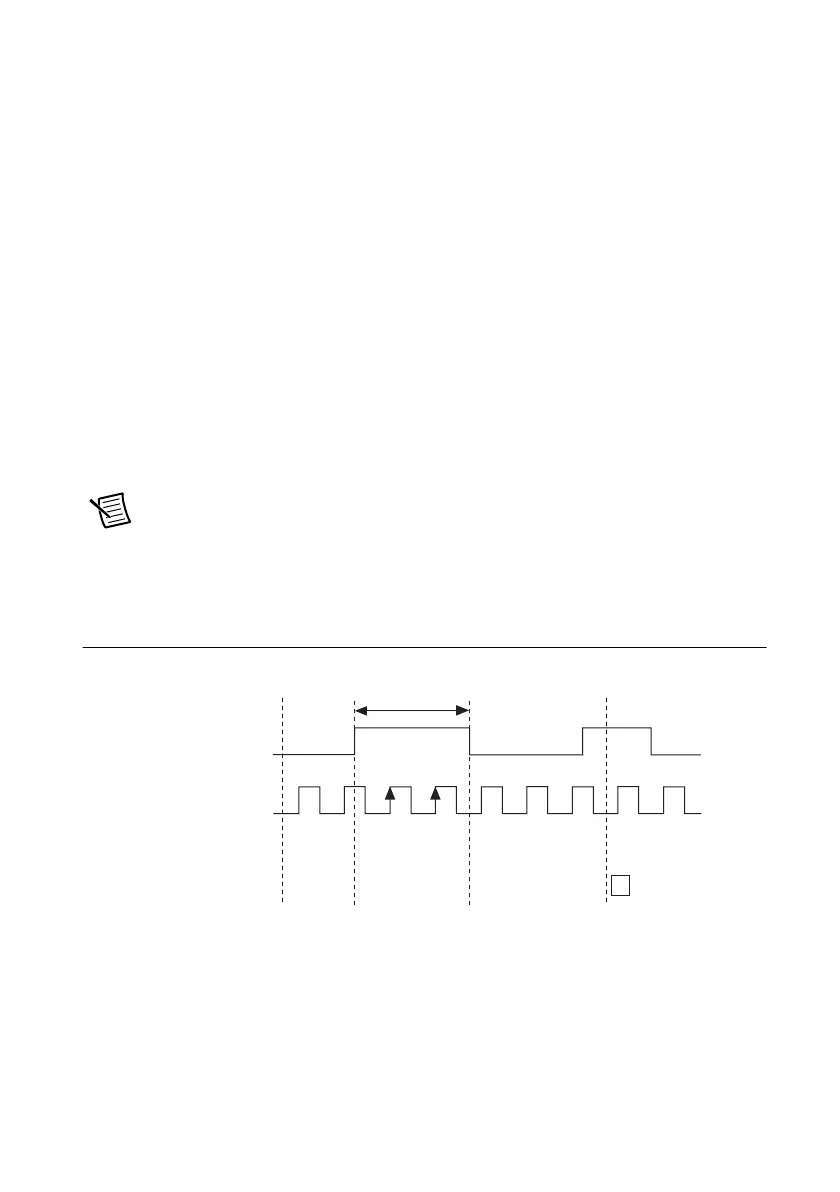
In a Pulse-Width measurement task, the counter measures the duration of a pulse on a signal.
Figure 3-20 shows an example of a Pulse-Width measurement.
Figure 3-20. Pulse-Width Measurement
The Pulse-Width can be calculated based on the number of edges of the Counter Timebase that
occur during the pulse on the signal-to-measure. This measurement begins when the
signal-to-measure first enters the active state. If the counter is armed while the signal-to-measure
is already in the active state, then the counter will wait for the next transition to the active state
to begin the measurement.
Counter Timebase
Signal to Measure
Counter Value
Read Value
10
2
2
DAQmx
Start Task
DAQmx Read
Sample
 Loading...


