4-6 | ni.com
Chapter 4 PFI
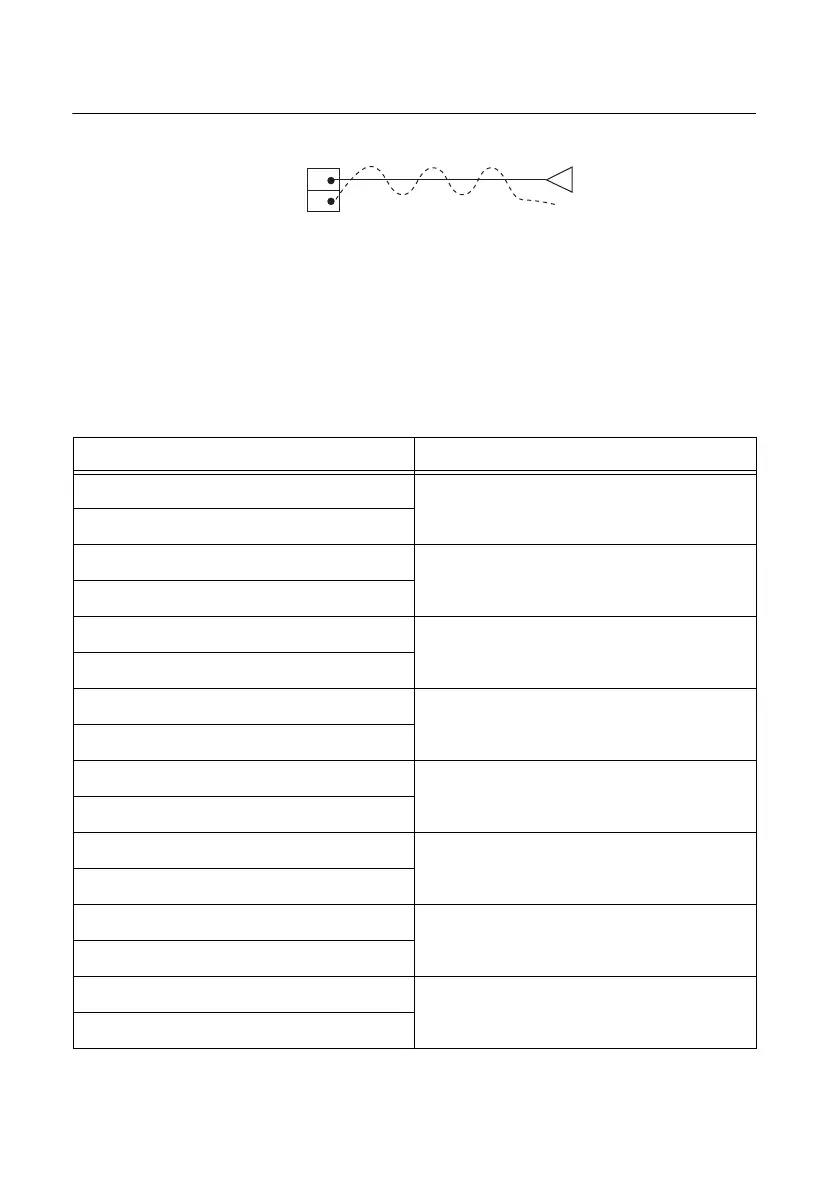
Figure 4-5. Twisted-Pair Wiring
The NI 6612 has 40 PFI pins. Each PFI pin is paired with a particular GND pin. The SH68-68-D1
cable twists each PFI pin with its corresponding GND pin. Table 4-2 shows the corresponding
GND pin for each PFI pin. If you are using a 68-pin screw terminal accessory or designing your
own accessory, make sure to connect your GND signal to the appropriate GND pin as shown in
this table. If you are using the BNC-2121, simply connect your GND signal to the nearest
GND pin.
Table 4-2. Signals and D GND Pin Number on
68-Pin Screw Terminal Accessory
PFI/DIO Number Pin Number for D GND
PFI 0 / P0.0 11
PFI 1 / P0.1
PFI 2 / P0.2 46
PFI 3 / P0.3
PFI 4 / P0.4 14
PFI 5 / P0.5
PFI 6 / P0.6 49
PFI 7 / P0.7
PFI 8 / P0.8 50
PFI 9 / P0.9
PFI 10 / P0.10 18
PFI 11 / P0.11
PFI 12 / P0.12 20
PFI 13 / P0.13
PFI 14 / P0.14 55
PFI 15 / P0.15
PFI 39 Pin 2
GND Pin 36
GND
Output of External Device
68-Pin Screw
Terminal Accessory
 Loading...


