© National Instruments | 5-1
5
Counter Signal Routing and
Clock Generation
NI 6612 has flexible signal routing features. Signals can be routed to or from the following
sources:
• User input through the PFI terminals
• Any of the eight counters
• The digital I/O circuits
• Other devices in your system through RTSI
• User input through the PXI_Star terminal
• Clocking circuitry
Clock Routing
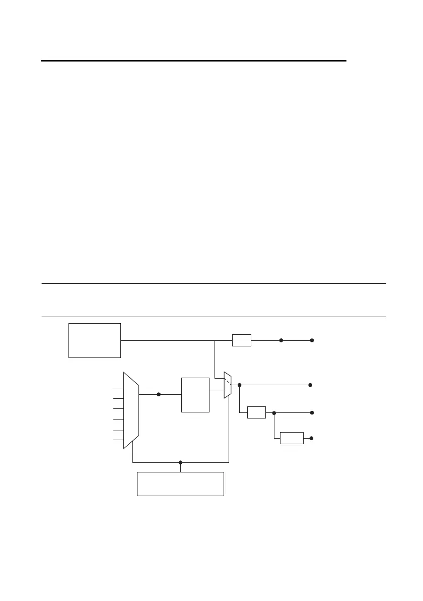
Figure 5-1 shows the clock routing circuitry of an NI 6612 device.
Figure 5-1. Clock Routing Circuitry
PXI_Trigger <0..7>
Onboard
100 MHz
Oscillator
External
Reference
Clock
(To RTSI <0..7>,
PXI_Trigger <0..7>
& PFI <0..39>
Output Selectors)
10 MHz RefClk
PLL
÷ 5
÷ 200
DAQmx Timing Property
RefClk.Src
PXIe_CLK100
PXI_STA R
100 MHz
Timebase
100 kHz
Timebase
20 MHz
Timebase
PFI
PXIe-DSTAR<A, B>
RTSI <0..7>
÷ 10
 Loading...


