2-6 | ni.com
Chapter 2 Digital I/O
Device Routes tab in MAX. Refer to Device Routing in MAX in the NI-DAQmx Help or the
LabVIEW Help for more information.
If the NI 6612 receives a DI Sample Clock when the FIFO is full, it reports an overflow error to
the host software.
You can sample data on the rising or falling edge of DI Sample Clock.
Routing DI Sample Clock to an Output Terminal
You can route DI Sample Clock out to any PFI <0..39> terminal. The PFI circuitry inverts the
polarity of DI Sample Clock before driving the PFI terminal.
Other Timing Requirements
The NI 6612 only acquires data during an acquisition. The device ignores DI Sample Clock
when a measurement acquisition is not in progress. During a measurement acquisition, you can
cause the device to ignore DI Sample Clock using the DI Pause Trigger signal.
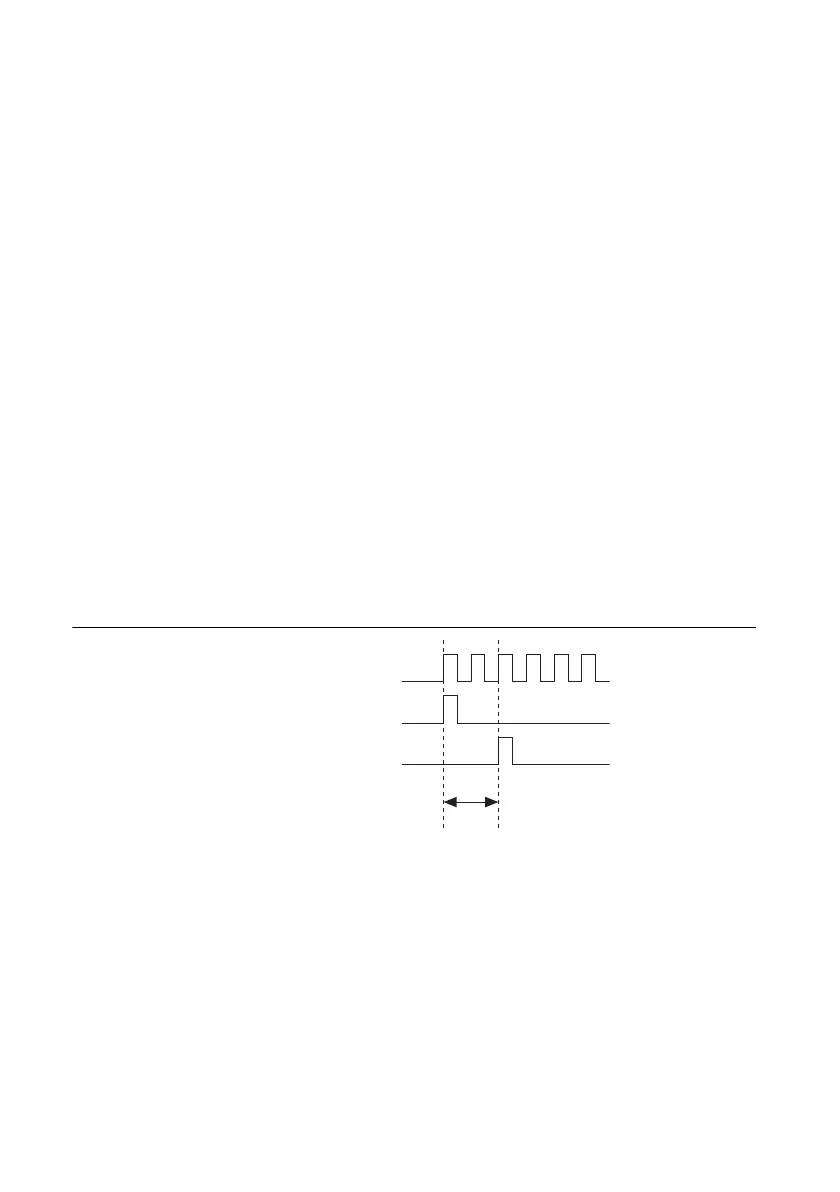
The DI timing engine on the device internally generates DI Sample Clock unless you select some
external source. DI Start Trigger starts this timing engine and either software or hardware can
stop it after a finite acquisition completes. When using the DI timing engine, you also can specify
a configurable delay from DI Start Trigger to the first DI Sample Clock pulse.
By default, this delay is set to two ticks of the DI Sample Clock Timebase signal.
Figure 2-4. DI Sample Clock and DI Start Trigger
DI Sample Clock Timebase Signal
By default, the NI 6612 routes the onboard 100 MHz timebase to DI Sample Clock Timebase.
You can route many signals to DI Sample Clock Timebase. To view the complete list of possible
routes, see the Device Routes tab in MAX. Refer to Device Routing in MAX in the NI-DAQmx
Help or the LabVIEW Help for more information.
DI Sample Clock Timebase is not available as an output on the I/O connector. DI Sample Clock
Timebase is divided down to provide one of the possible sources for DI Sample Clock. The
DI Sample Clock Timebase
DI Start Trigger
DI Sample Clock
Delay
from
Start
Trigger
 Loading...


