© National Instruments | 2-5
NI 6612 User Manual
Digital Waveform Acquisition
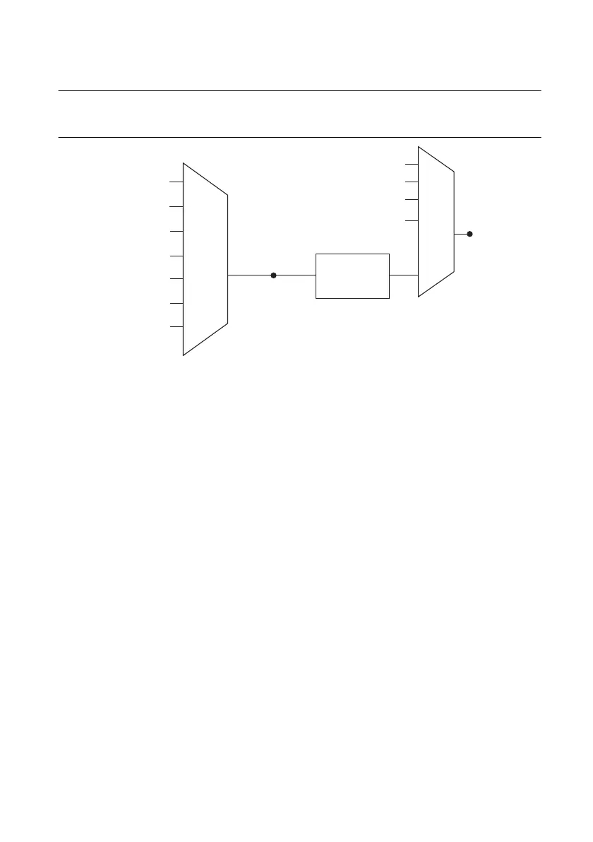
Figure 2-3 summarizes all of the timing options provided by the digital input timing engine.
Figure 2-3. Digital Input Timing Options
You can acquire digital waveforms on the Port 0 DIO lines. The DI waveform acquisition FIFO
stores the digital samples. The NI 6612 has a DMA controller dedicated to moving data from the
DI waveform acquisition FIFO to system memory. The device samples the DIO lines on each
rising or falling edge of a clock signal, DI Sample Clock.
You can configure each DIO line to be an output, a static input, or a digital waveform acquisition
input.
The following digital input timing signals are featured:
• DI Sample Clock Signal*
• DI Sample Clock Timebase Signal
• DI Start Trigger Signal*
• DI Reference Trigger Signal*
• DI Pause Trigger Signal*
Signals with an * support digital filtering. Refer to the
PFI Filters section of Chapter 4, PFI, for
more information.
DI Sample Clock Signal
The device uses the DI Sample Clock (di/SampleClock) signal to sample the Port 0 terminals
and store the result in the DI waveform acquisition FIFO.
By default, the programmable clock divider drives DI Sample Clock (see Figure 2-3). You can
route many signals to DI Sample Clock. To view the complete list of possible routes, see the
PFI, RTSI, PXI_Trigger
PXI_STA R
20 MHz Timebase
100 kHz Timebase
PXI_CLK10
Programmable
Clock
Divider
DI Sample Clock
Timebase
PFI, RTSI, PXI_Trigger
PXI_STA R
Ctr
n Internal Output
DI Sample Clock
100 MHz Timebase
DSTAR <A..B>
DSTAR <A..B>
 Loading...


