© National Instruments | 5-5
NI 6612 User Manual
Routing Options
You can change the signal routing from the default by configuring DAQmx properties. Refer to
Chapter 3,
Counters, for more information about changing the signal routed to each counter.
To view a complete list of possible routes for each signal, use the Device Routes table for
NI 6612 in Measurement & Automation Explorer (MAX). To view this table:
1. Launch Measurement & Automation Explorer (MAX) by navigating to Start»
All Programs»National Instruments»Measurement & Automation Explorer, or
(Windows 8) by clicking Measurement & Automation Explorer from NI Launcher.
2. Expand My System»Devices and Interfaces in the configuration tree on the left to view
your device.
3. Left-click your device to select it.
4. Click the Device Routes tab at the bottom of the middle pane to see routes that can be made
within your device.
Matching Routing Terminology
NI-DAQmx and the Device Routes table in MAX use different terminology for counter signals.
The counters each have the following inputs: Source, Gate, Aux, HW Arm, A, B, Z, Sample
Clock. MAX uses these names. However, the counter inputs have different functions depending
on what type of measurement you are taking. NI-DAQmx uses names that reflect the function
of the signal for each particular type of measurement.
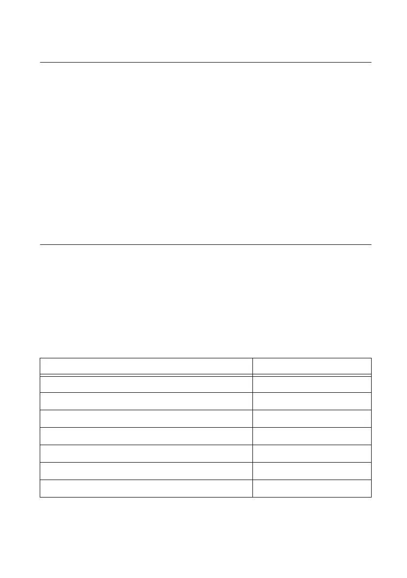
Table 5-3 shows the mapping from NI-DAQmx terms to MAX terms, with n as an integer
representing the Counter number.
Table 5-3. Matching Routing Terminology
NI-DAQmx Property Counter Input Signal
ArmStart.DigEdge.Src CtrnArmStartTrigger
CI.CountEdges.CountReset.Term CtrnGate
CI.CountEdges.DirTerm CtrnB
CI.CountEdges.Term CtrnSource
CI.Encoder.AInputTerm CtrnA
CI.Encoder.BInputTerm CtrnB
CI.Encoder.ZInputTerm CtrnZ
 Loading...


