3-14 | ni.com
Chapter 3 Counters
• CI.CtrTimebase.Src—To change the signal used as the counter timebase, set this property
to a different terminal.
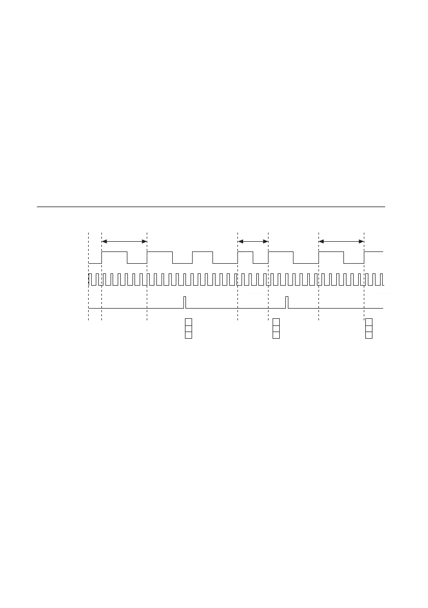
Sample Clock (without Averaging)
With this method, for each sample clock the counter detects the last full period of the
signal-to-measure that occurs before the sample clock. The counter measures the duration of this
one period by counting the number of cycles (T2) of the timebase.
At each sample clock, the device stores T2 in a buffer. DAQmx reads this value, and uses the
known frequency of the timebase (f
k
), to calculate the frequency of the input signal (f
x
) as:
Figure 3-16. Frequency Measurement: Sample Clock without Averaging
To use the Sample Clock (without Averaging) method, configure the following:
• DAQmx Create channel (CI-Frequency)—Use this VI or function to create the channel.
• DAQmx Timing (Sample Clock)—Use this VI or function to set the number of samples,
samples clock source, and other properties.
• CI.Freq.EnableAveraging—Set this property to False.
By default, the counter measures the frequency on a default PFI terminal (refer to Chapter 5,
Counter Signal Routing and Clock Generation, for more information) and use an onboard
100 MHz clock as the timebase. To change the signals used for this measurement, configure the
following:
• CI.Freq.Term—The signal-to-measure comes from an input terminal. To change the
signal-to-measure, set this property to a different terminal.
• CI.CtrTimebase.Src—To change the signals used as the counter timebase, set this
property to a different terminal.
Sample
Clock
DAQmx
Start Task
Buffer
6
646
4
6
4
6
6
Sample 1 Sample 2 Sample 3
Signal to
Measure (f )
Counter
Timebase (f )
x
k
 Loading...


