© National Instruments | 2-19
NI 6612 User Manual
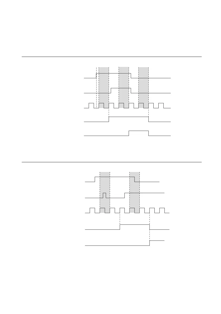
The behavior for each transition can be thought of as a state machine. If a line transitions and
stays high for two consecutive filter clock edges, then one of two options occurs:
• Case 1—If no transitions have occurred on the other lines, the transition propagates on the
second filtered clock edge, as shown in Figure 2-14.
Figure 2-14. Case 1
• Case 2—If an additional line on the bus also has a transition during the filter clock period,
the change is not propagated until the next filter clock edge, as shown in Figure 2-15.
Figure 2-15. Case 2
Digital Input P0.A
Digital Input P0.B
Filter Clock
Filtered Input A
Filtered Input B
Stable Stable Stable
Digital Input P0.A
Digital Input P0.B
Filter Clock
Filtered Input A
Filtered Input B
Not Stable Not Stable
 Loading...


