GB
7
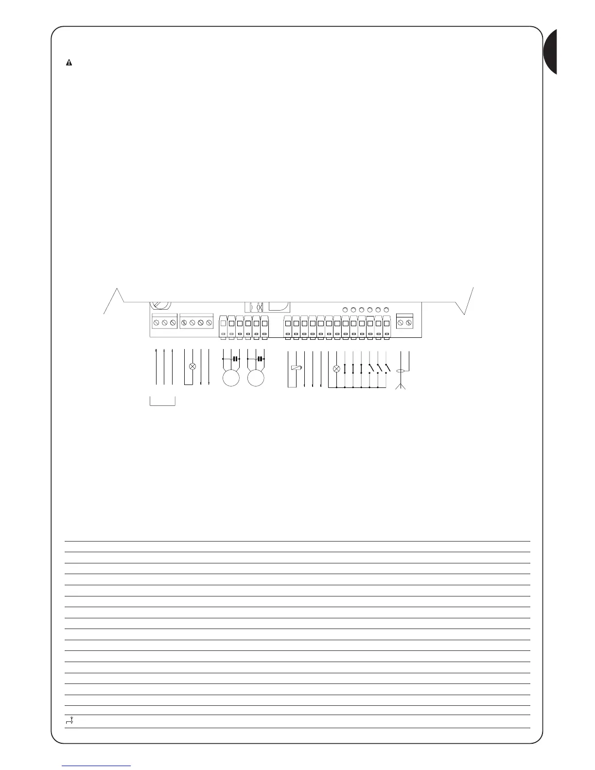
Terminals Function Description
1-2-3 : Power supply = Mains power line
4 – 5 : Flashing light = Output for connecting flashing light to mains voltage (Max. 100W)
6 – 7 : Courtesy light = Clean contact output for courtesy light connection (Max. 5A)
8-9-10 : Motor1 = Motor 1 control output, max. motor power 1/2 Hp
11-12-13 : Motor2 = Motor 2 control output, max. motor power 1/2Hp
15 -16 : Electric lock = 12 Vdc output for electric lock activation, max. power 25W
17 – 18 : 24 Vac = Power supply to 24Vac services ( Max. 150 mA)
19 : Phototest = Phototest output - “TX” power supply to photocells - (Max. 75 mA)
20 : Common = Common for all inputs
21 : AC light = 24 Vac output for open gate indicator light (Max. 2W)
22 : Stop = Input with “Stop” function (Stop and short reverse run)
23 : Photo = Input for safety devices
24 : Photo1 = Input for additional safety device
25 : Step by step (PP) = Input for cyclic movement (“Open” – “Stop” – “Close” – “Stop”)
26 : Open = Input for opening function
27 : Close = Input for closing function
: Aerial = Input for the radio receiver aerial
2.2) Electrical connections:
ATTENTION: To safeguard the operator and avoid damaging the components, make sure that the control unit is switched
off while you are wiring or plugging in the various cards
• Power the control unit using a 3 x 1.5 mm2 cable; should the distance between the unit and the earth connection exceed 30m, install
an earth plate near the unit.
• Use wires with a minimum cross-section of 0.25 mm2 to connect extra-low voltage safety circuits.
• Use shielded wires if the length exceeds 30m and only connect the earth braid to the control unit side.
• Do not make connections to cables in buried boxes even if they are completely watertight.
• If the inputs of the Normally Closed (NC) contacts are not used, they should be jumped with the “24V common” terminal except for the
photocell inputs if the phototest function is enabled. For further information please see the “Phototest” paragraph.
• If there is more than one (NC) contact on the same input, they must be connected in SERIES.
• If the inputs of the Normally Open (NA) contacts are not used they should be left free.
• If there is more than one (NA) contact on the same input, they must be connected in PARALLEL.
• The contacts must be mechanical and potential-free; no stage connections are allowed, such as those defined as "PNP", "NPN", "Open
Collector", etc.
2.2.1) Electrical diagram
2.2.2) Description of connections
The following table provides a brief description of the possible control unit output connections.

 Loading...


