EN
10 – English
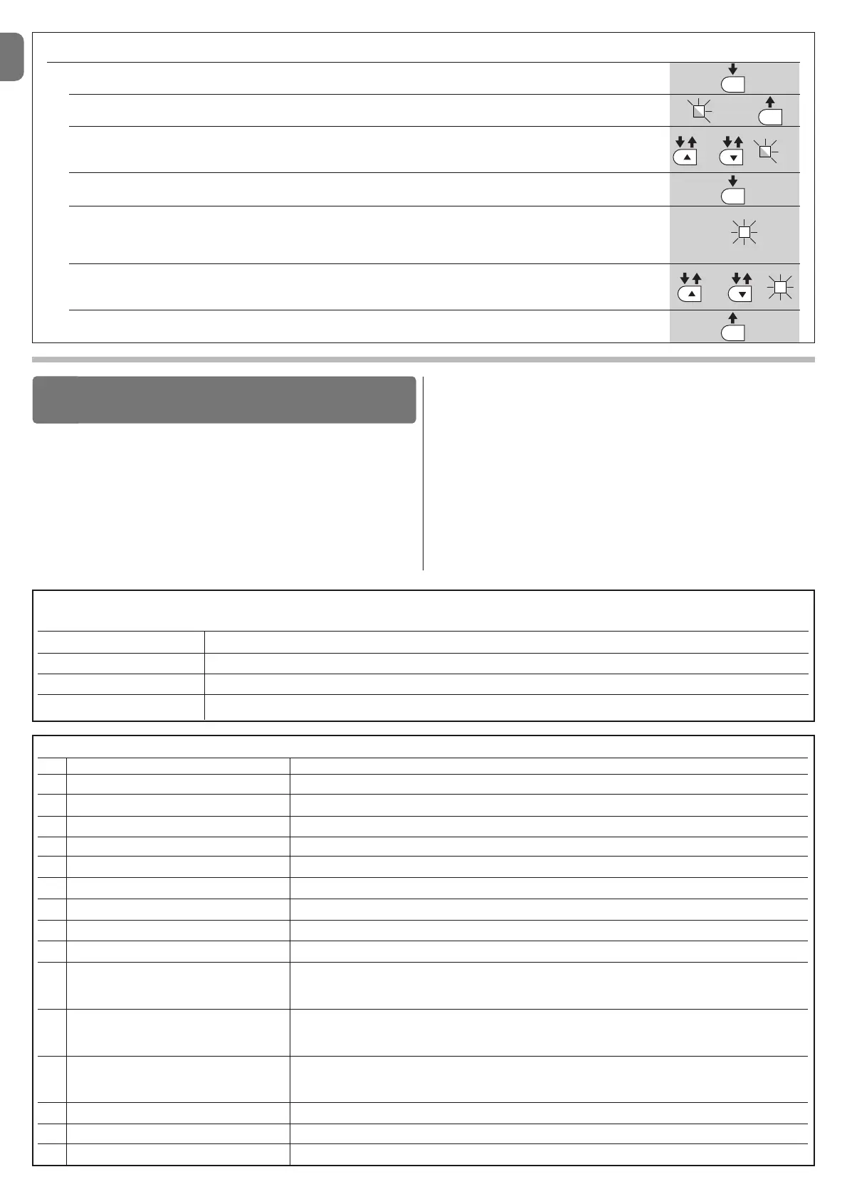
TABLE 12 - Fault log
01. Press and hold down the “Set” key for approx. 3 seconds;
02. Release the key when LED “L1” starts flashing;
03. Press keys “” or “u” to move from the flashing LED to L8 LED (“input LED”) for the “Fault log” parameter;
04. Press and hold the “Set” key through to completion of point 06;
05. Wait approx. 3 seconds until the LEDs representing the levels corresponding to the manoeuvres with faults illuminate.
The LED L1 indicates the result of the most recent manoeuvre while L8 indicates the eighth-to-last manoeuvre.
If the LED is on this means that a fault has occurred; if the LED is off, everything is normal;
06. Press keys “” and “u” to select the required manoeuvre: the corresponding LED performs a number of flashes equal
to those normally performed by the flashing light;
07. Release the “Set” key.
L1
or
and
3 s
3 s
L8
The following accessories are envisaged for POP (optional): receivers in the
family SMXI, OXI, the programmer Oview, the solar power panel Solemyo and
buffer battery mod. PS124 .
8.1 - Connecting a radio receiver
The control unit has a connector for connecting radio receivers (optional acces-
so ries) belonging to the SMXI and OXI families. To connect a receiver, discon-
nect power from the control unit and proceed as shown in fig. 16. Table 13 and
Table 14 show the commands corresponding to the outputs on the control
unit.
FURTHER DETAILS
8
8.2 - Connection and installation of the back-up battery
mod. PS124
IMPORTANT! - The battery must only be connected to the control unit after
all the phases of installation and programming have been completed, as
the battery constitutes a source of emergency power.
To arrange connection to the Solemyo system, follow the stages of assembly
fig. 17.
8.3 - Connection of the Oview programmer
The control unit has a BusT4 connector to which the Oview programming unit
can be connect, and which allows the complete rapid management of the instal-
lation and maintenance phase as well as the diagnosis of the entire automation
system. To access this connector, proceed as shown in fig. 18 and connect the
TABLE 13
SMXI / SMXIS or OXI / OXIFM / OXIT / OXITFM in mode I or Mode II
Output N°1
Output N°2
Output N°3
Output N°4
“S.S.” (Step by Step) command
“Partial opening 1” command
“Open” command
“Close” command
TABLE 14 - OXI / OXIFM /OXIT / OXITFM in extended mode II
N° Command Description
1 Step by step
2 Partial opening 1
3 Open
4 Close
5 Stop
6 Apartment block
7 Step by Step
8 Partial open 2
9 Partial open 3
10 Open and block
11 Close and block
12 Block automation
13 Release
14 On Timer Courtesy light
15 On-Off Courtesy light
“S.S.” (Step by Step) command
“Partial opening 1” command
“Open” command
“Close” command
Stops manoeuvre
Apartment block control
Gives command even when automation is blocked or commands are in progress
Partial open (Opening of leaf M2 to 1/2 of normal opening)
Partial open (Opening of two leafs to 1/2 of normal opening)
It causes an opening manoeuvre, after which the automation is blocked; the control unit accepts no further
commands with the exception of “Step by step high priority”, “Release” automation and (from Oview only)
the commands “Release and close” and “Release and open”
It causes a closure manoeuvre, after which the automation is blocked; the control unit accepts no further
commands with the exception of “Step by step high priority”, “Release” automation and (from Oview only )
the commands “Release and close” and “Release and open”
It causes the manoeuvre to stop and the automation to block; the control unit accepts no further commands
with the exception of “Step by step high priority”, “Release” au to mation and (from Oview only ) the com-
mands “Release and close” and “Release and open”
It causes the automation to be released and normal operation to resume
The Courtesy light comes on with timed turning off
The Courtesy light turns on and off in step-by-step mode

 Loading...