Chapter 5 Assembling and Connection of the System
25
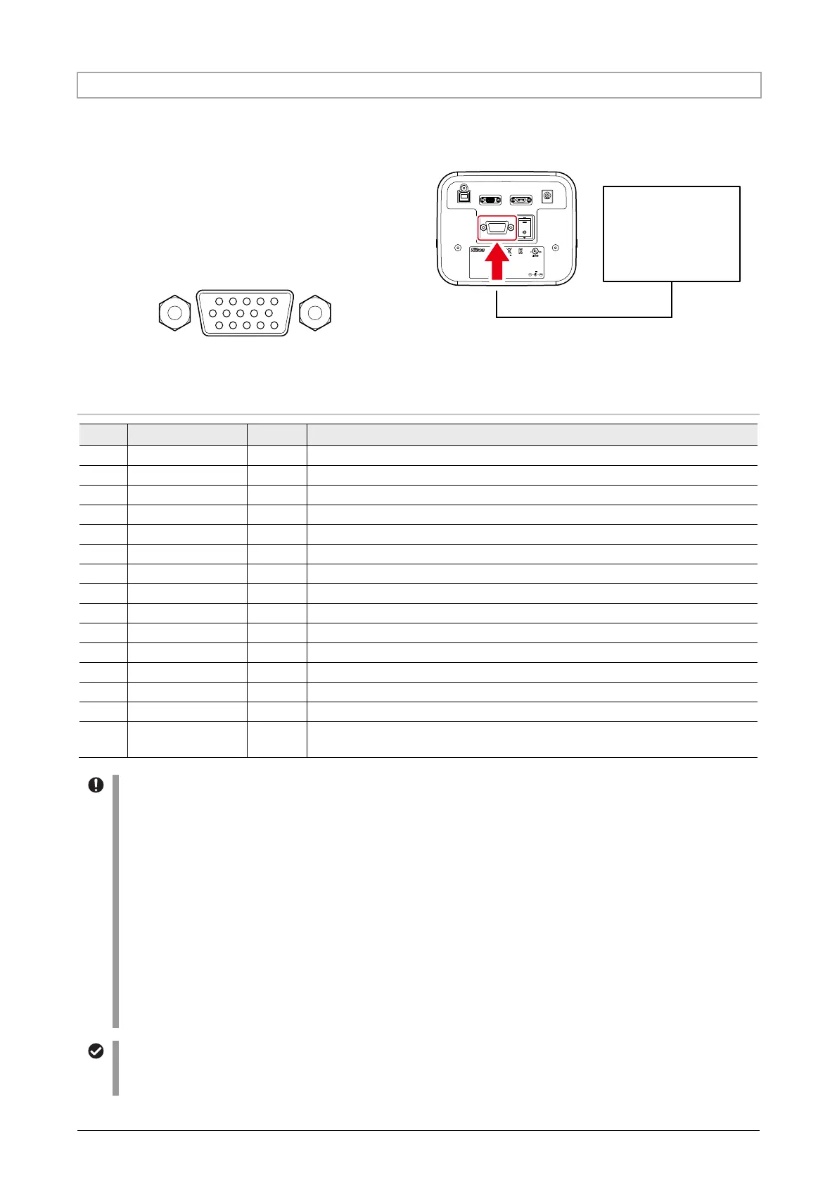
5.4.3 Connecting an External Trigger Generation Device (TRIGGER Connector)
When an external trigger generation device is connected to this product, illumination can be controlled in
conjunction with a trigger such as a camera trigger.
To use a trigger generation device, connect an
appropriate cable to the TRIGGER connector of this
product. Note that the TRIGGER cable is not
provided.
The pin layout of the TRIGGER connector is as
shown below.
15
610
1115
High density D-Sub 15 pin (female)
USB
REMOTE CONTRO L
DC
TRIGGER
D
-
LEDI
4N75
INSPECTION
EQUIPMENT
R
-
R
-
NEc
-
SD
-
LEDI
INPUT
12VDC , 3.3A
830001
This device c omplies with Part 15 of t he FCC Rules.
Operation i s subject to the follo wing two consiti ons:
(1) this device may not cause harmful interference, and
(2) this dev ice must accept any in terference rece ived,
including interference taht may cause undesired operation.
CAN ICES-3 (A)/NMB-3 (A)
MADE IN JAPAN
TOKYO JAPAN
Connecting a trigger generation device (TRIGGER connector)
Pin layout of the TRIGGER connector
Pin Signal name I/O Function
1 TRG1 IN Turn LED1 (385 nm) on and off. (H: On. L: Off)
2 TRG2 IN Turn LED2 (475 nm) on and off. (H: On. L: Off)
3 TRG3 IN Turn LED3 (550 nm) on and off. (H: On. L: Off)
4 TRG4 IN Turn LED4 (621 nm) on and off. (H: On. L: Off))
5 TRGALL IN Turn all the LEDs on and off. (H: On. L: Off)
6 GND
-
Ground
7 GND
-
Ground
8 NC
-
Not connected
9 NC
-
Not connected
10 NC
-
Not connected
11 STS1 OUT Outputs the on/off status of LED1 (385 nm). (H: On; L: Off)
12 STS2 OUT Outputs the on/off status of LED2 (475 nm). (H: On; L: Off)
13 STS3 OUT Outputs the on/off status of LED3 (550 nm). (H: On; L: Off)
14 STS4 OUT Outputs the on/off status of LED4 (621 nm). (H: On; L: Off)
15 STSALL OUT
Outputs the logical OR of all the LED status. (H: One or more LED is on, L:
All the LEDs are off)
Connecting the TRIGGER connector
• The input and output voltage ranges of the TRIGGER connector must fall into the following range:
Input voltage range (TRG1 to TRG4, and TRGALL)
• LOW level : 0.0 V to 0.5 V
• HI level : 2.5 V to 5.2 V
* Never apply an instantaneous voltage outside the range from
-
0.5 V to 7.0 V.
Output voltage range (STS1 to STS4, and STSALL)
• LOW level : 0.0 V to 0.5 V
• HI level : 4.5 V to 5.1 V
* The value when load resistance RL is 100 kΩ or above.
If any other load is connected, the above voltage level may not be achieved.
• Do not apply an external voltage to the output terminals (STS1 to STS4, and STSALL). Doing so may cause
failure.
• Leave the unused terminals (pin 8 to 10) not connected.
Limitation when using the external trigger
When the external trigger is enabled, any LED on/off operations other than from the external trigger will not be
accepted (brightness control is allowed).
External trigger
generation device
 Loading...