1.2.3 LED Status Indicators
In addition to details of detected events being displayed on the LCD,
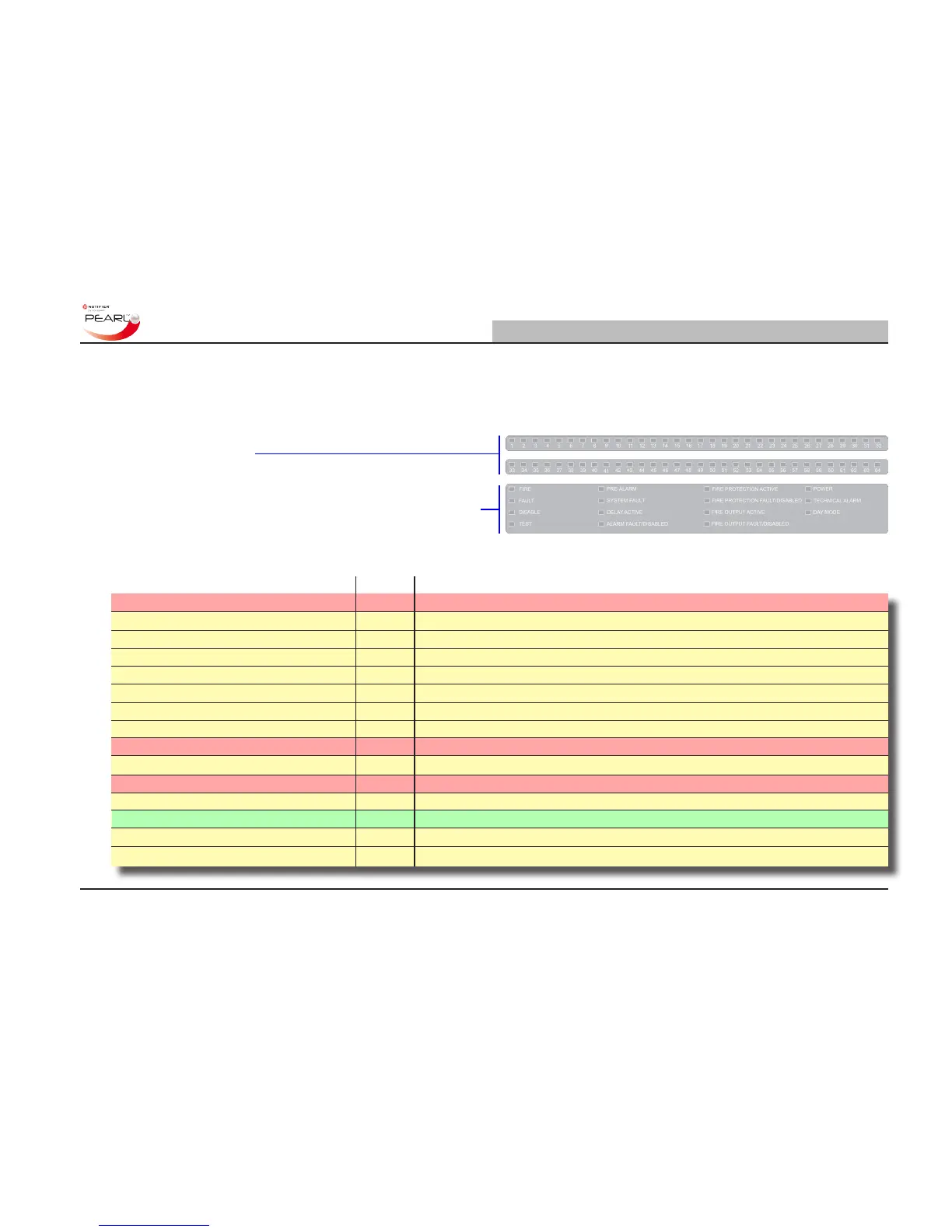
a number of LED status indicators are provided in the lower area
of the panel fascia.
The upper two banks of LEDs are zone re LEDs (zones 1 to 64)
and may not be tted.
The lower bank of LEDs contains all the required system status
indicators to support the primary indicator, i.e. the LCD. With most
panel- or loop-related events these LEDs are able to provide a quick
indication of the possible cause of the panel status change.
The following status indicators are provided:
LED Name Colour Description
FIRE Red A re condition exists.
FAULT Yellow A fault condition exists.
DISABLE Yellow One or more devices are disabled.
TEST Yellow A test condition has been entered,
PRE-ALARM Yellow A pre-alarm condition exists.
SYSTEM FAULT Yellow The system has failed.
DELAY ACTIVE Yellow Programmed delay(s) are in effect.
ALARM FAULT/DISABLED Yellow A re output, if congured, is disabled or has a fault.
FIRE PROTECTION ACTIVE Red An output to the re protection system, if congured, is active.
FIRE PROTECTION FAULT/DISABLED Yellow An output to the re protection system, if congured, is disabled or has a fault.
FIRE OUTPUT ACTIVE Red The re relay (and re output if congured) is active.
FIRE OUTPUT FAULT/DISABLED Yellow The re relay is disabled or the Fire output (if congured) is disabled or has a fault.
POWER Green System power (mains or battery) is available.
TECHNICAL ALARM Yellow Technical Alarm device activated.
DAY MODE Yellow The DAY MODE has been entered.

 Loading...


