EasyManua.ls Logo

Nvidia JETSON TX2 User Manual

Nvidia JETSON TX2
103 pages
To Next Page IconTo Next Page
To Previous Page IconTo Previous Page
Page #19 background imageLoading...
Page #19 background image
NVIDIA Jetson TX2/TX2i OEM Product Design Guide
JETSON TX2/TX2i OEM PRODUCT | DESIGN GUIDE | 20180618 19
Touch Interrupt (TOUCH_INT)
GPIO6_TOUCH_INT
51
USB VBUS Detect (USB_VBUS_DET)
USB0_VBUS_DET
53
GPIO Expansion 0 Interrupt (GPIO_EXP0_INT)
GPIO_EXP0_INT
54
Modem Wake AP (MDM_WAKE_AP)
GPIO16_MDM_WAKE_AP
55
Battery Low (BATLOW#)
BATLOW#
56
GPIO Expansion 1 Interrupt (GPIO_EXP1_INT)
GPIO_EXP1_INT
58
USB Vbus Enable 0 (USB_VBUS_EN0)
USB_VBUS_EN0
61
USB Vbus Enable 1 (USB_VBUS_EN1)
USB_VBUS_EN1
62
Ambient Light Proximity Interrupt (ALS_PROX_INT)
GPIO8_ALS_PROX_INT
63
Modem Coldboot (MDM_COLDBOOT)
GPIO18_MDM_COLDBOOT
64
Force Recovery (FORCE_RECOV#)
FORCE_RECOV#
67
Sleep (SLEEP_L)
SLEEP#
68
Figure 14. Deep Sleep (SC7) Entry/Exit Sequence
CARRIER_PWR_ON
VIN_PWR_BAD#
VDD_IN
RESET_OUT#
SC7 Entry SC7 Exit
CARRIER_STBY#
(Tegra X2 SOC_PWR_REQ)
VDD_3V3_SLP
VDD_5V0_SLP
VDD_12V_SLP
VDD_5V0_HDMI_CON
SC7 Entry/Exit Trigger
Carrier Board VDD_1V8
3.8 Optional Auto-Power-On Support
Jetson TX2 and Jetson TX2i both optionally support Auto-Pow er-On. This allow s the platform to pow er on w hen VDD_IN is first
powered, instead of w aiting for a pow er button press. For Jetson TX2, to enable this feature, the CHARGER_PRSNT# pin
should be tied to GND. For Jetson TX2i, which uses a different PMIC, the POWER_BTN# pin needs to be held high. As there
is a pull-up on the module, the POWER_BTN# pin can be left floating on the carrier board. If a design w ill support both Jetson
TX2 and Jetson TX2i and needs to power on w ithout a button press (Auto-Pow er-On), the CHARGER_PRSNT# pin should be
tied to GND, and the POWER_BTN# pin should be left unconnected.
3.8.1 Jetson TX2 Auto-Power-On Details
This section provides guidance for modifying a carrier board design to power the platform on w hen VDD_IN is first pow ered,
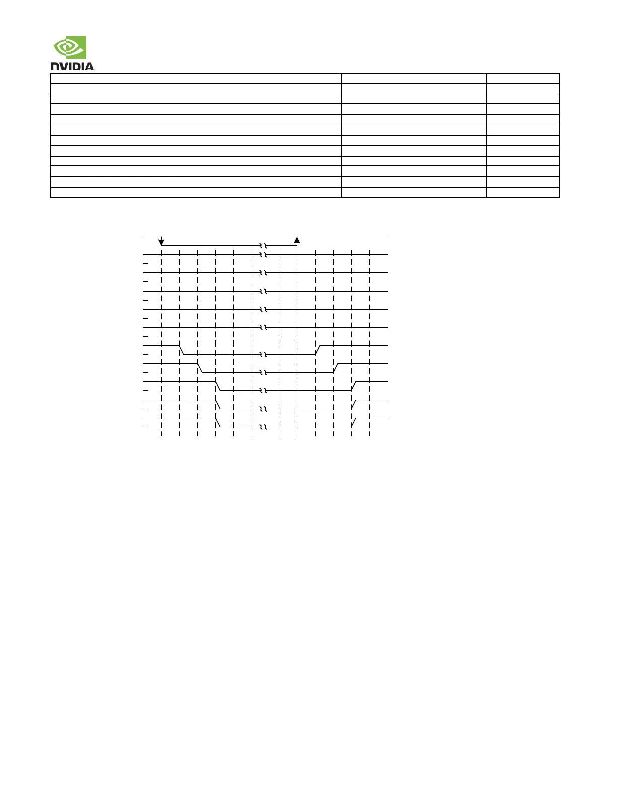
instead of w aiting for a power button press. In order to pow er the system on w ithout a pow er button, a specific sequence is
required betw een the time the VDD_IN pow er is connected and the CHARGER_PRSNT# pin on the module is driven low . The
CHARGER_PRSNT# pin connects to the module PMIC and requires a minimum delay of 300ms from the point VDD_IN reaches
its minimum level (5.5V) before it can be driven low . Jetson TX2/TX2i includes circuitry on the module to support Auto-Pow er-
On. In order to enable this feature, the CHARGER_PRSNT# pin should be tied to GND.

Other manuals for Nvidia JETSON TX2

Question and Answer IconNeed help?

Do you have a question about the Nvidia JETSON TX2 and is the answer not in the manual?

Nvidia JETSON TX2 Specifications

General IconGeneral
Storage32 GB eMMC 5.1
Operating SystemLinux for Tegra
GPUNVIDIA Pascal architecture with 256 CUDA cores
Memory8 GB LPDDR4
Connectivity802.11ac WLAN, Bluetooth
Video Decode4K @ 60 fps (HEVC), 4K @ 60 fps (H.264)
Power7.5W | 15W
CameraUp to 6 cameras (CSI)
USBUSB 3.0
OthersCAN, UART, SPI, I2C, GPIOs
CPUDual Denver 2 64-Bit CPUs + Quad ARM A57 CPUs

Summary

Document Abstract

Introduction to the Design Guide

Document References

Lists related documents and models for further information.

Abbreviations and Definitions

Defines common abbreviations used throughout the document.

Jetson TX2/TX2i Overview

Jetson TX2/TX2i Module Overview

Describes the Jetson TX2/TX2i module components and available interfaces.

Power Management

Supply Allocation

Details the allocation of power rails within the module's power subsystem.

Main Power Sources/Supplies

Illustrates main power connections, sources, and control signals on the carrier board.

Power Sequencing

Explains the critical power-up sequence involving key control signals.

Module Power-on Type Detection & Control

Power & Voltage Monitoring

Module Power Monitor

Details how module power monitors indicate supply status via WARN or CRIT outputs.

Deep Sleep (SC7) Mode

Optional Auto-Power-On Support

Jetson TX2i Auto-Power-On Details

Details the requirements for auto-power-on support for Jetson TX2i modules.

General Routing Guidelines

USB, PCIe, and SATA Interfaces

USB Interface Details

Details USB 2.0 and USB 3.0 pin descriptions and design guidelines.

PCIe Interface Details

Describes the PCIe controller, lane configurations, and design guidelines.

SATA Interface Details

Details the Gen 2 SATA controller implementation and design guidelines.

Gigabit Ethernet Interface

Display Interfaces

MIPI DSI Interface

Details MIPI DSI data lanes, configurations, and pin descriptions.

eDP, DP, and HDMI Interfaces

Describes eDP, DP, and HDMI interface capabilities and pin mapping.

MIPI CSI (Video Input)

SDIO/SDCARD/eMMC Interfaces

SD Card Interface Details

Explains the standard SD socket connection and signal routing requirements.

Audio Interfaces

Integrated WLAN/BT (Jetson TX2 Only)

Miscellaneous Interfaces

I2C Interface Details

Details the nine I2C controllers, pin descriptions, and interface mapping.

SPI Interface Details

Describes the three SPI interfaces, pin descriptions, and connection diagrams.

UART Interface Details

Covers the five UARTs, pin descriptions, and typical assignments.

Strapping Pins Configuration

Module Pads and Behavior

MPIO Pad Behavior when Associated Power Rail is Enabled

Explains MPIO pad behavior when associated power rail is enabled or disabled.

Internal Pull-ups for CZ Type Pins at Power-on

Details internal pull-up behavior for CZ type MPIO pads at power-on.

Unused Interface Terminations

Unused MPIO Interfaces

Identifies unused MPIO pins supporting SFIO and GPIO capabilities.

Design Checklist

General Layout Guidelines

Overview of Layout Guidelines

Explains the importance of trace and via characteristics for signal integrity.

Via Guidelines

Provides guidelines on via count, placement, and their impact on power distribution.

Stack-Ups

Reference Design Stack-Ups

Explains the importance of stack-up definition for design.

Transmission Line Primer

Background on Transmission Lines

Discusses PCB transmission line characteristics affecting signal integrity.

Physical Transmission Line Types

Describes microstrip and stripline transmission line types.

Driver Characteristics

Identifies key driver characteristics for signal integrity and transmission speed.

Receiver Characteristics

Explains key receiver concepts for optimum signal integrity.

Design Guideline Glossary

Jetson TX2/TX2i Pin Descriptions

Related product manuals