EasyManuals Logo
Home>Nvidia>Microcontrollers>JETSON TX2

Nvidia JETSON TX2 User Manual

Nvidia JETSON TX2
103 pages
To Next Page IconTo Next Page
To Previous Page IconTo Previous Page
Page #69 background imageLoading...
Page #69 background image
NVIDIA Jetson TX2/TX2i OEM Product Design Guide
JETSON TX2/TX2i OEM PRODUCT | DESIGN GUIDE | 20180618 69
12.4 Fan
Jetson TX2/TX2i provides PWM and Tachometer functionality for controlling a fan as part of the thermal solution. Information on
the PWM and Tachometer pins/functions can be found in the following locations:
Module Pin Mux:
This is used to configure the FAN_PWM & FAN_TACH pins. The FAN_PWM pin is configured as GP_PWM4.
The FAN_TACH pin is configured as NV_THERM_FAN_TACH.
Tegra X2 Technical Reference Manual:
Functional descriptions and related registers can be found in the TRM for the FAN_PWM (PWM chapter) &
FAN_TACH (Tachometer chapter) functions.
Jetson Developer Kit Carrier Board Specification:
The document contains the maximum current capability of the VDD_5V0_IO_SYS supply in the Interface Pow er
chapter (VDDIO_5V0_IO_SLP comes from that supply). The fan is powered by this supply on the module
Developer Kit carrier board.
Table 78. Fan Pin Descriptions
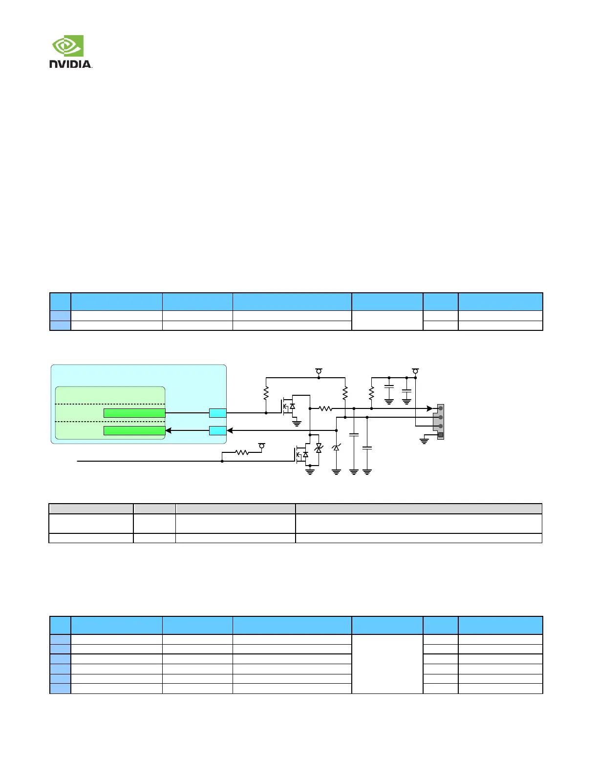
Pin #
Module Pin Name
Tegra Signal
Usage/Description
Usage on the Carrier
Board
Direction
Pin Type
C16
FAN_PWM
GPIO_SEN6
Fan PWM
Fan
Output
CMOS 1.8V
B17
FAN_TACH
UART5_TX
Fan Tach
Input
CMOS 1.8V
Figure 42. Fan Connection Example
VDD_5V0_IO_SLPVDD_1V8
G
S
D
10pF
4
3
2
1
10pF
PS_VDD_FAN_DISABLE
(G PIO Expander P04)
G
S
D
4.7k
100k
10k
10uF
0.1uF
100k
Fan
Header
100
VDD_5V0_IO_SYS
Jetson TX2/TX2i
Tegra Fan
GPIO_SEN6
AO
FAN_PWM
FAN_TACH
UART5_TX
C16
B1 7
UART
Table 79. Fan Signal Connections
Module Name
Type
Termination
Description
FAN_PWM
O
Fan Pulse Width Modulation: Connect through FET as shown in the Fan
Connections figure.
FAN_TACH
I
ESD diode to GND
Fan Tachometer: Connect to TACH pin on fan connector.
12.5 CAN
Jetson TX2/TX2i brings tw o CAN (Controller Area Netw ork) interfaces out to the main connector.
Table 80. CAN Pin Descriptions
Pin #
Module Pin Name
Tegra Signal
Usage/Description
Usage on the Carrier
Board
Direction
Pin Type
C20
CAN_WAKE
CAN_GPIO4
CAN Wake
GPIO Expansion
Header
Input
CMOS 3.3V
E18
CAN0_ERR
CAN_GPIO5
CAN #0 Error
Input
CMOS 3.3V
D18
CAN0_RX
CAN0_DIN
CAN #0 Receive
Input
CMOS 3.3V
D19
CAN0_TX
CAN0_DOUT
CAN #0 Transmit
Output
CMOS 3.3V
C19
CAN1_ERR
CAN_GPIO3
CAN #1 Error
Input
CMOS 3.3V
D17
CAN1_RX
CAN1_DIN
CAN #1 Receive
Input
CMOS 3.3V

Other manuals for Nvidia JETSON TX2

Questions and Answers:

Question and Answer IconNeed help?

Do you have a question about the Nvidia JETSON TX2 and is the answer not in the manual?

Nvidia JETSON TX2 Specifications

General IconGeneral
BrandNvidia
ModelJETSON TX2
CategoryMicrocontrollers
LanguageEnglish

Related product manuals